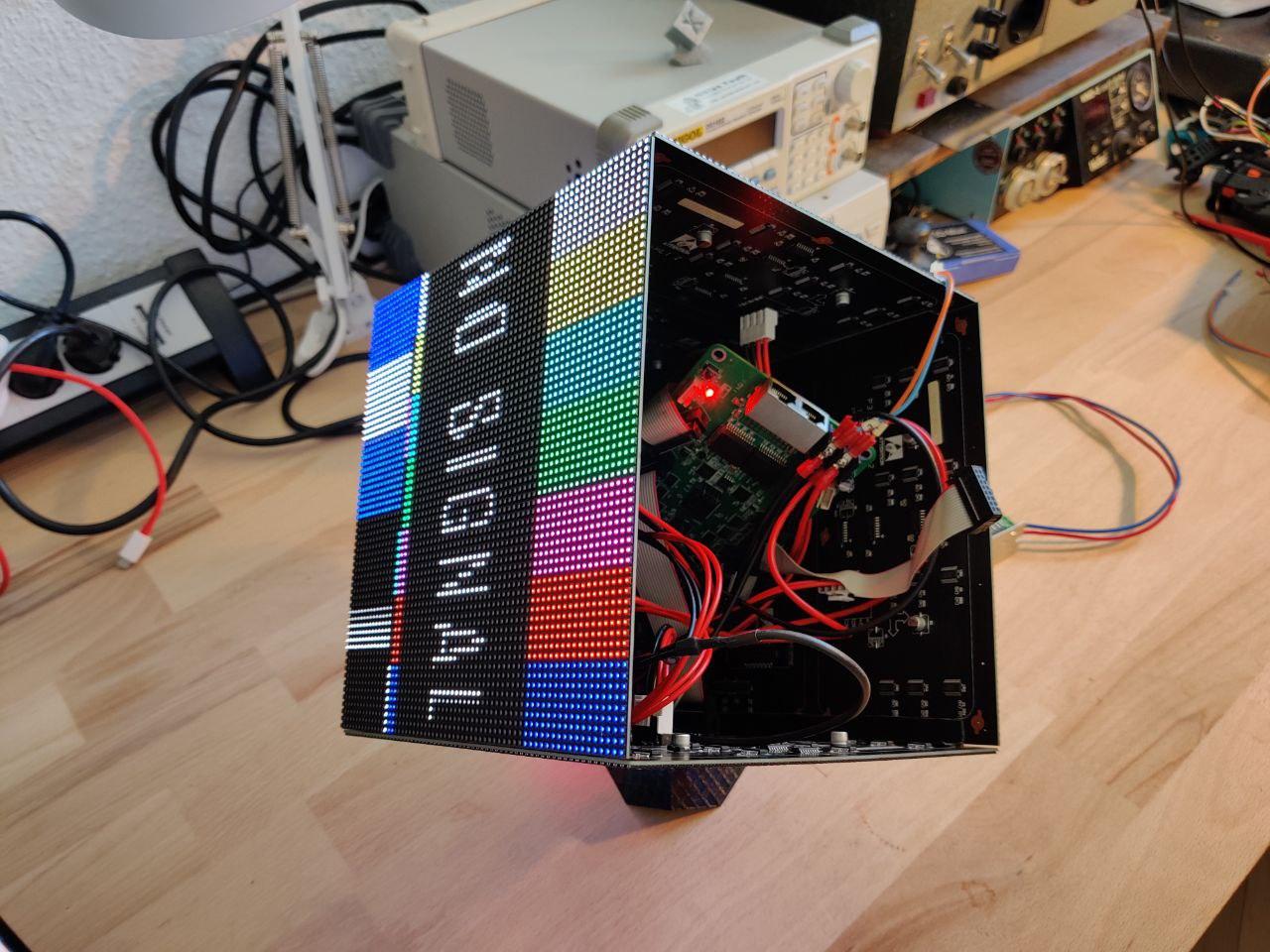
This repo contains open source software and fpga hardware to use the Colorlight 5a-75B 7.0 LED card to, well, drive HUB75e RGB LED panels. While this seems pretty unnecessary at the first glance, is actually super cool, especially if you want to build a LED cube. Through the Colorlight was designed and is sold to drive such panels, it originally requires an additional, expensive capture card. With this new firmware you can use it straight away in you network and send UDP packets to it.
- supports 6 LED displays with 64x64 Pixels each
- RGB666 based protocol (before gamma correction), hardware gamma correction, 7 bit brightness control
- Fast connection recovery
- Displays a test screen while no frames are received
- IP and ports are hardcoded. Maybe add some DIP switches? (requires a hardware hack).
- Show IP on the test screen.
- Setting LED panel parameters / resolution via UDP.
To reproduce this, you will need multiple things:
- A Colorlight 5a-75B 7.0 LED card (e.g. from Aliexpress)
- A JTAG programmer (e.g. Glasgow: https://github.com/GlasgowEmbedded/glasgow)
- Some Pin Headers (to solder on the JTAG interface)
- HUB75e 64x64 LED panels (other resolutions are supported by editing ledpanel.v)
- yosys, nextpnr and prjtrellis installed
After you set up all required tools, you can build the bitstream:
cd fpga/syn/
make top.svf
If you don't want to edit anything and just want to reproduce this exact project, you can also just use the top.svf to flash the fpga straight away. To flash, connect you JTAG programmer to the JTAG interface (see https://github.com/q3k/chubby75/blob/master/5a-75b/hardware_V7.0.md for pinout).
Possible Glasgow command to write so SRAM (only temporarily, eg. for testing):
glasgow run jtag-svf -V 3.3 --pin-tck 0 --pin-tms 1 --pin-tdi 2 --pin-tdo 3 top.svf
Or with openocd:
openocd -f openocd.cfg -c "transport select jtag; init; scan_chain; svf top.svf; shutdown; quit"
If you want to permanently flash the bitstream, use
cd fpga/syn/
make flash.svf
(many thanks to Greg Davill and tnt for debugging this for the write-protected colorlight flash!)
Then again:
glasgow run jtag-svf -V 3.3 --pin-tck 0 --pin-tms 1 --pin-tdi 2 --pin-tdo 3 flash.svf
Or with openocd:
openocd -f openocd.cfg -c "transport select jtag; init; scan_chain; svf flash.svf; shutdown; quit"
In principle, 6 out of any of the 8 HUB75 ports could be used. However I prefer to have J1 available for debugging, and for J4, one of the pins currently remains unknown. Therefore, J2, J3, J5, J6, J7 and J8 are used to drive the displays. You can change this in top.lpf if you like (see chubby75 for updated pinouts).
The protocol is very basic. For each pixel, one UDP packet can be sent, containing 4 bytes:
MSB     Byte 3      LSB   MSB     Byte 2      LSB   MSB     Byte 1      LSB   MSB     Byte 0      LSB

31 30 29 28 27 26 25 24 | 23 22 21 20 19 18 17 16 | 15 14 13 12 11 10 09 08 | 07 06 05 04 03 02 01 00

      MSB - pos Y - LSB   MSB - pos X - LSB MSB  -  Red   - LSB MSB -  Green  - LSB MSB - Blue -  LSB

      05 04 03 02 01 00   05 04 03 02 01 00 05 04   03 02 01 00 05 04 03 02   01 00 05 04 03 02 01 00
The panel to drive is selected by the port the UDP packet is addressed to. Since this is done in the fpga by using a bitmask, the ports appear a bit unusual. However, they just share a common MSB, and the LSBs are used to mask what panel to address. This way you can also address multiple panels to display the same content, if you like.
As you can see, a maximum of 256x256 px per panel could be achived using this protocol by daisy - chaining some more panels per channel.
Also, color resolution is 6bit per color, = RGB666. However, this is before gamma correction, so the actual perceived resolution is much more.
For examples on how to send these UPD packets, see the sw directory.
IP can be changed here:
colorlight-led-cube/fpga/liteeth.yml
Line 11 in e69b52f
Recompile with make ../liteeth_core.v
Ports can be changed here:
This defines the MSB bitmask for the panels ports.
This project relies on a lot of amazing work done by others. Notably: Christian Fibich for initially pouring the bits and pieces around the colorlight efforts together, and initially driving LED panels with it. In fact, much of the project structure was made by him. I just debugged, added some features, and wrote this docs.
Claire Wolf for yosys and nextpnr of course, but also for this hub75 driver code that was modified to work with 64x64 panels, and support gamma correction: http://svn.clifford.at/handicraft/2015/c3demo/fpga/ledpanel.v This is also a good starting point to change resolution back to eg. 32x16 px.
Enjoy Digital for the amazing work around LiteX and Liteeth, used in this project. Also the colorlight board is officially supported by LiteX, so getting started was pretty straightforward and fun.
Jan Henrik Hemsing for writing some python scripts to stream video to the displays.
