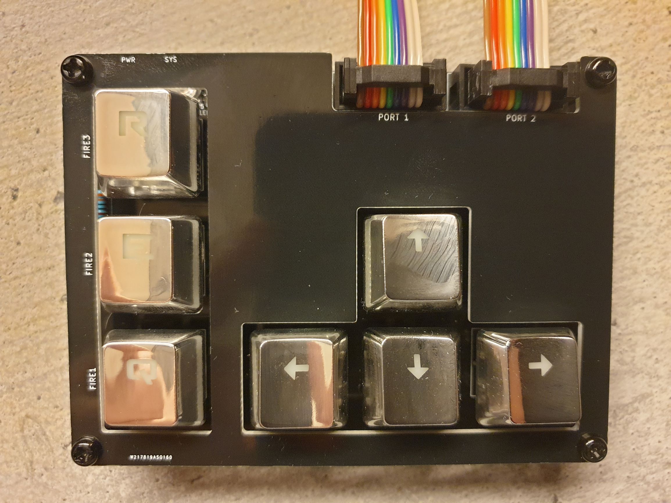
Congratulations on the taking the leap to build my slightly over-complicated 7-key keyboard/joystick, now probably compatible with most of your favourite vintage computers. It can be built or configured in a few ways, so take a look at the configuration document so that you'll have an idea of what you want to do with it - pay particular mention to whether you'd require any of the features provided by the Arduino Pro Micro and which of the separate adapters you will need.
The first step in building it, is what you've already done - figuring out what you wanted out of it in the first place! The second step is taking stock of which parts you don't already have, check out the BOM (Bill of Manufacturing) below for a somewhat detailed of everything I used when building the prototype. Note that any adapters you'll want will have their own BOM.
You should be able to get most from the more reputable electronic component oligopolists, but because of extreme import fees where I live - those are for the most part not an option for me (I can't afford to pay €40 worth of fees to get €10 worth of parts at ten times the cost). What I do instead is order most things from ebay and AliExpress, you'll have to do a bit more of guesswork to find the correct parts - additionally, delivery times are most probaly to be counted in number of weeks and not days.
My best suggestion on getting what you need the first time, is to use the search function and start with the description I've added, compare it to the pictures and order whichever looks to be the closest - if it's a cheap part, just get a few different ones! Pin headers usually come in 40-pin strips, both dual row and single row ones will be needed - add some right-angle ones as well (you'll just break off what you need). For some parts such as common resistor values, M3 nylon hex standoffs and switches it might be preferable to get a kit instead of the specific kind (the are usually referred to as a parts kit "assortment").
Order what you need, set the components aside until you're ready to start assembling things.
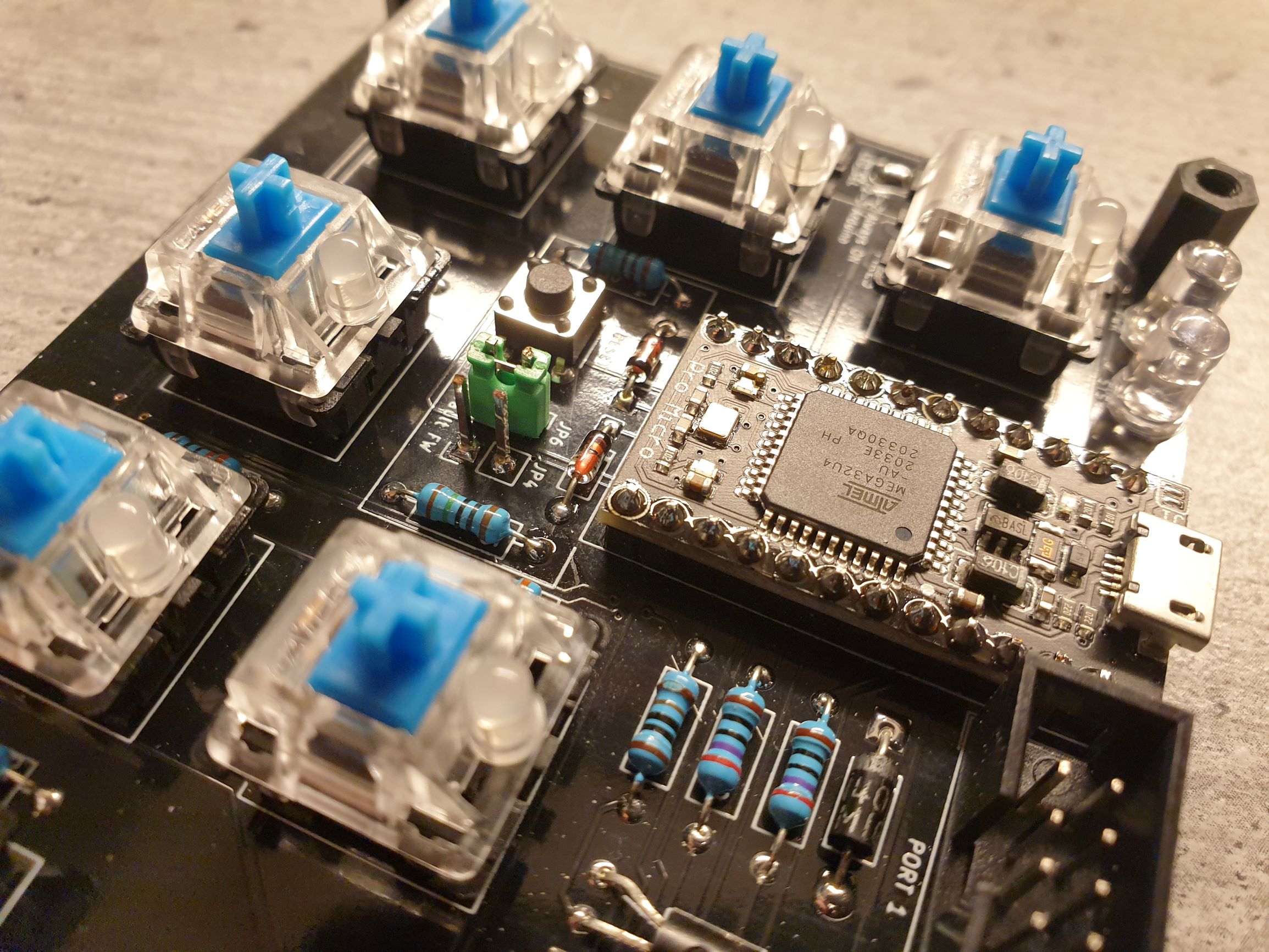
When ready to start soldering things into place, start by installing the physically smaller parts such as the resistors then move on up vertically to the taller parts in order to make things easier on yourself. Note that if you intend to install the underglow LEDs, these should be soldered onto the board after the Cherry MX switches (the longest LED pin goes into the round hole). The actual Cherry MX switches themselves will usually take a bit of force to get into place, so make sure to push them firmly into place before finally soldering them permanently into place (removing solder is a lot harder to remove than it is to add it, so it is a good idea to check alignment more than once).
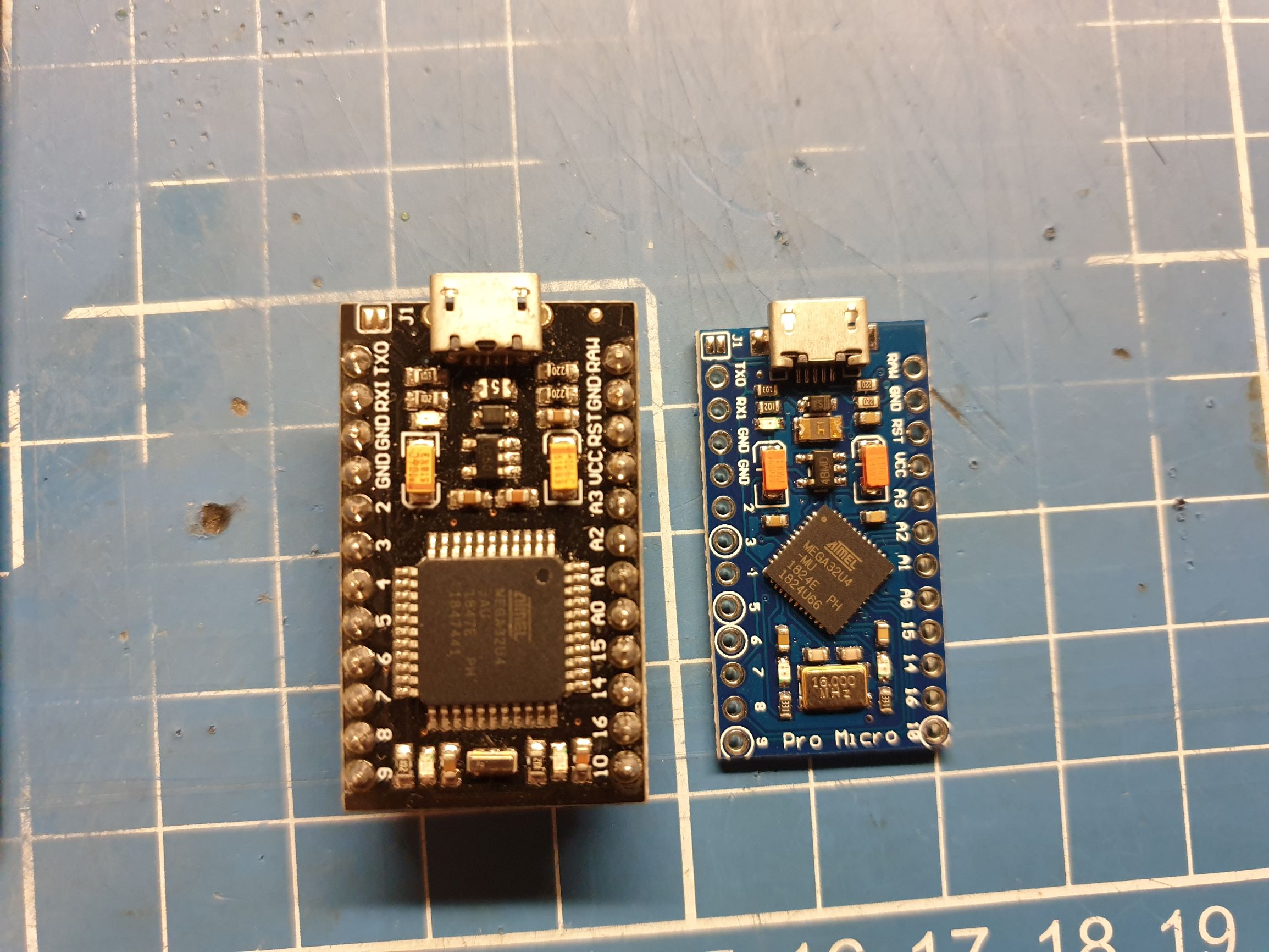
The Arduino Pro Micro unfortunately seem to come in physically different variations, the ones most common seem to be the ones shown above (at least those are the two I have, the black DIYmore branded unit is recommended for purely aesthetic reasons) - the C64 JoyKEY can use either of these, but you need to align it so that the pins are soldered in the correct place so do a bit of dry-fitting before commiting. The switch below it is needed if you accidentally try to flash it using the wrong settings in Arduino Studio, there is a separate page that details how to deal with the firmware.
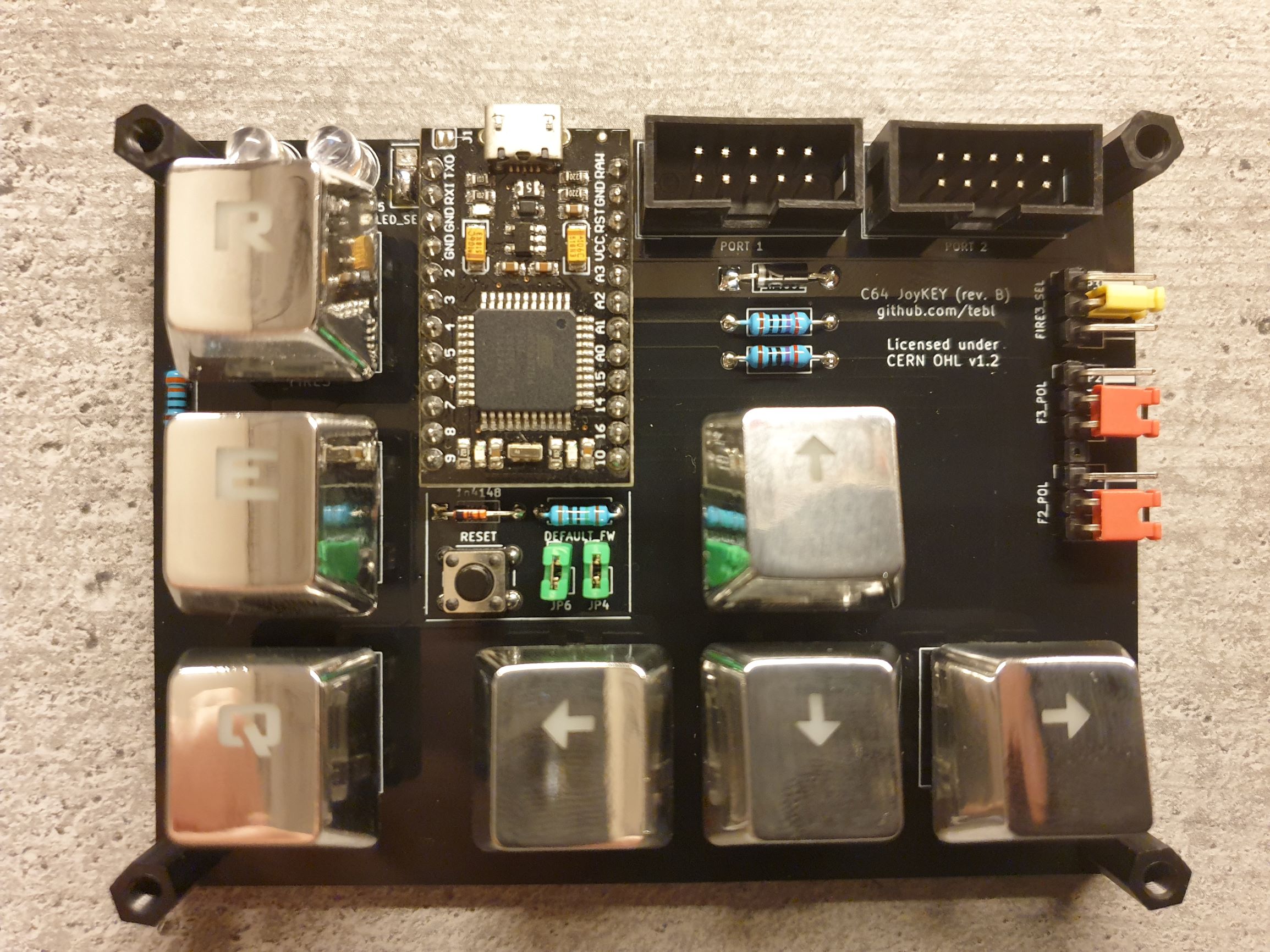
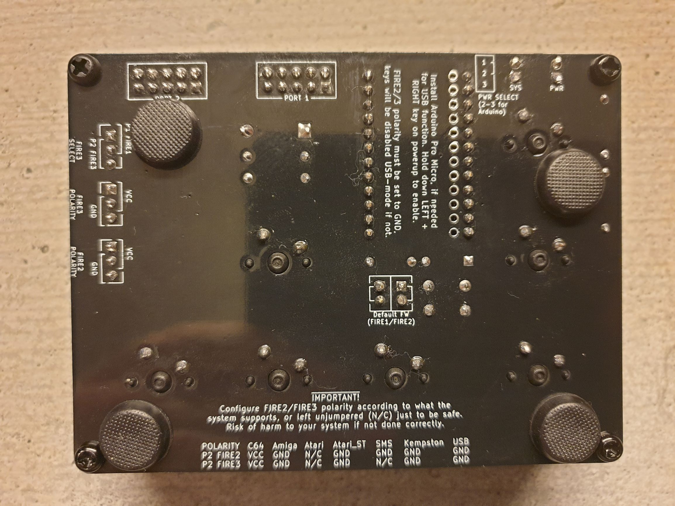
Notice the spot for two jumpers marked DEFAULT_FW (green in the picture above)? You'll need to add solder a piece of wire here, the leftovers you got when snipping the leads from the resistors can be used for this purpose. You need to do this even if you don't want the Arduino at all, the only reason not to do so is if you specifically want to use the autofire variant of the firmware instead. Installing pin headers here may lead to accidents as well as increase the required space between the module and faceplate. The same goes for the power links marked VCC_EN and ARD_EN. It may be tempting to install male pin headers and jumper caps here, but note that this would be a little too tall to fit under the faceplate - if you want them, you can either sand a bit off the top of the jumper caps or use some pliers to pull off the base of the pin headers (snip off a bit of the pins as well).
Next you'll want to screw together both pieces of PCBs, just put the female HEX standoffs of the size you want between them and add screws from both sides - this should make the whole thing stand up to some abuse (physical, not the MS-DOS game though you could try that one out later in DOSBOX).
Given that this is a PCB you'll be handling directly, it is probably a good idea to clean the flux residue left from soldering the connection points. It probably won't be very toxic, but depending on how much you spent on the solder you never know (China isn't exactly known for focusing on employee health and safety) - it is however a very sticky substance, so at the very least it's pretty annoying. It can be cleaned by pouring isopropyl alcohol (IPA), sometimes sold as contact cleaner or rubbing alcohol, over the board and scrubbing it with an old toothbrush to dissolve it evenly. You'll now have an evenly super-sticky board, but do NOT panic if this happens! Next step is to put some cloth over the board, pour more more IPA over the cloth and allow it to soak through to the board and rub it gently - when the alcohol has mostly evaporated, the stickyness should now be on the cloth instead. Phew!
Push the MX keycaps onto the top of the MX-switches, again you'll need to use a bit of careful force. You should now have a mostly completed unit, a recommended addition is to add some 3M bumpon adhesive rubber feet to the button - these are mostly there to keep the PCB from sliding around on your desk, but also keeps the solder points from scratching up your desk.
Those wanting to do a more complete build of the unit will probably have opted for the faceplate as well, it does not have any active (or passive components either) and is mostly just there to give the whole unit some added sturdyness. Both PCBs are screwed together using M3 hex spacers as well as screws to go with them, you can also use some of the nuts instead - if you got the M3 nylon hex standoff kit I recommended as part of the BOM. The space between needs to match the components you've installed on the module, to my eyes the 9mm ones look the best - though the 10mm ones seem to be a lot more commonly available on ebay (it's also in the kit). 8mm can also be used, but you'll need to install shorter LEDs (the kind listed as 5mm flat top LED or 5mm straw hat LED).
The last step is putting together some cables for your most common vintage systems, but if you only want to use it as a USB device then feel free to skip this step. Still here? Awesome.
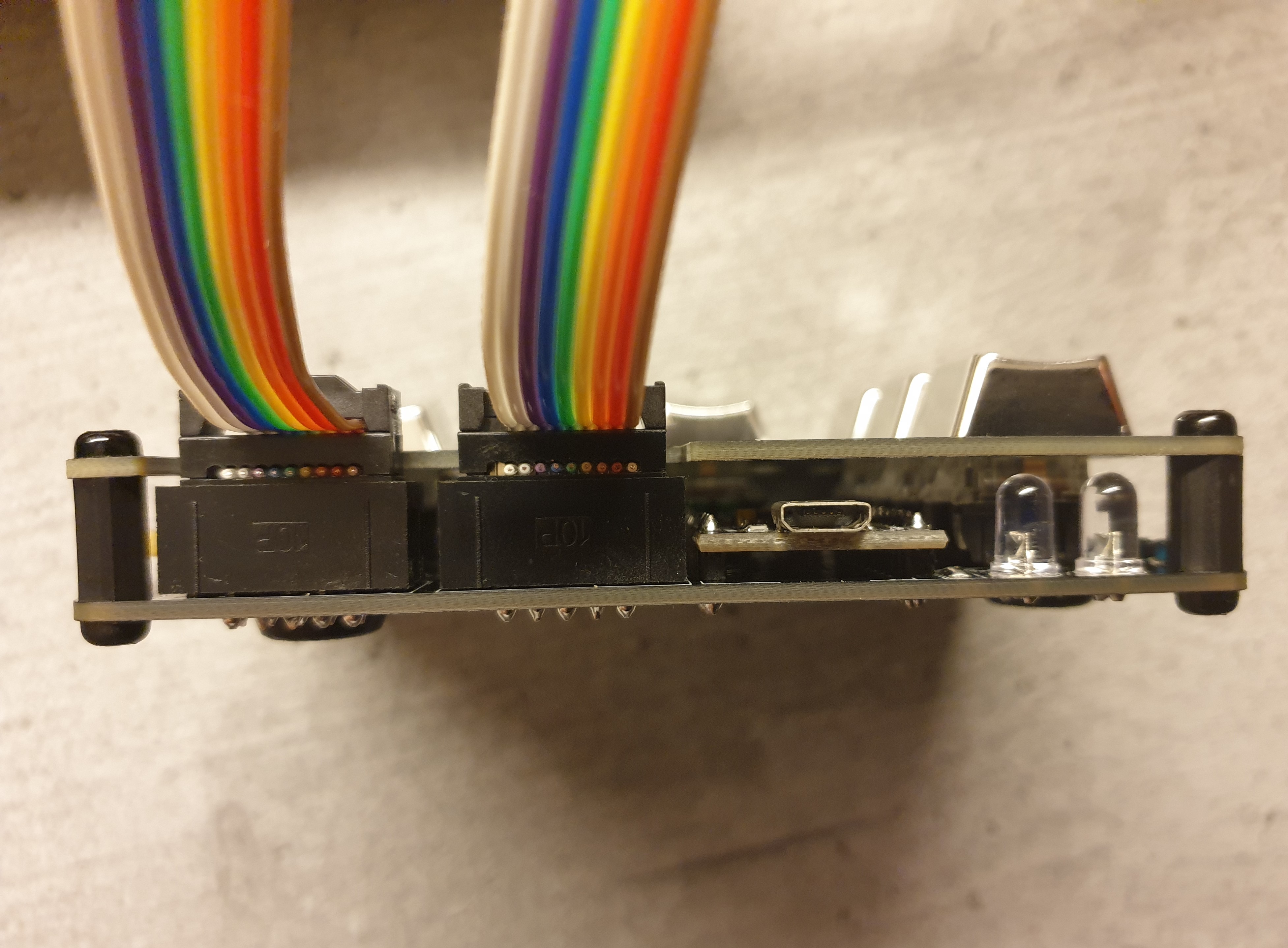
Soldering connectors is hard if you do it the hard way - the easiest way to get a cable suitable for use with C64 JoyKEY is adapting an existing cable. The ones I've used are usually listed as 2x5 pin AVR or JTAG cable, just cut off the end that doesn't fit into the board properly - the red stripe should be on the left side when plugging it into the board. The picture above should make things a bit easier to decipher, note that the 10th wire has been removed as it is not needed (only 9 pins on the DB9). The connectors I've used are described as female DB9 IDC, it is installed by lining up the red wire with pin 1 and pushing the clamp into place until you hear a click (a vice is helpful, that way you don't need to buy dedicated IDC connector tools).
I also bought some cables described DB9 female to female cable d-sub on AliExpress, these come with the DB9-side of the cable and you'll have to attach some 2x5 pin IDC connector instead - make sure to cut off the side you don't want (both'll work, the difference is if you want the cable pointing up or down when connected to the C64).
The IDC connector comes with two parts, just make sure to align pin 1 on both sides (there'll be a blank space on the right side as we only have 9 cables instead of 10). Align the cable the wrong way, then clamp it into place by pushing very hard against a table etc. Trim the short end and wrap the cable over the top, finally - attach the strain relief clip and push it into place.
If you're going to be playing on the Commodore 64 or Commodore Amiga, you'll probably want two of these cables for a selection of games - so, feel free to build yet another cable.
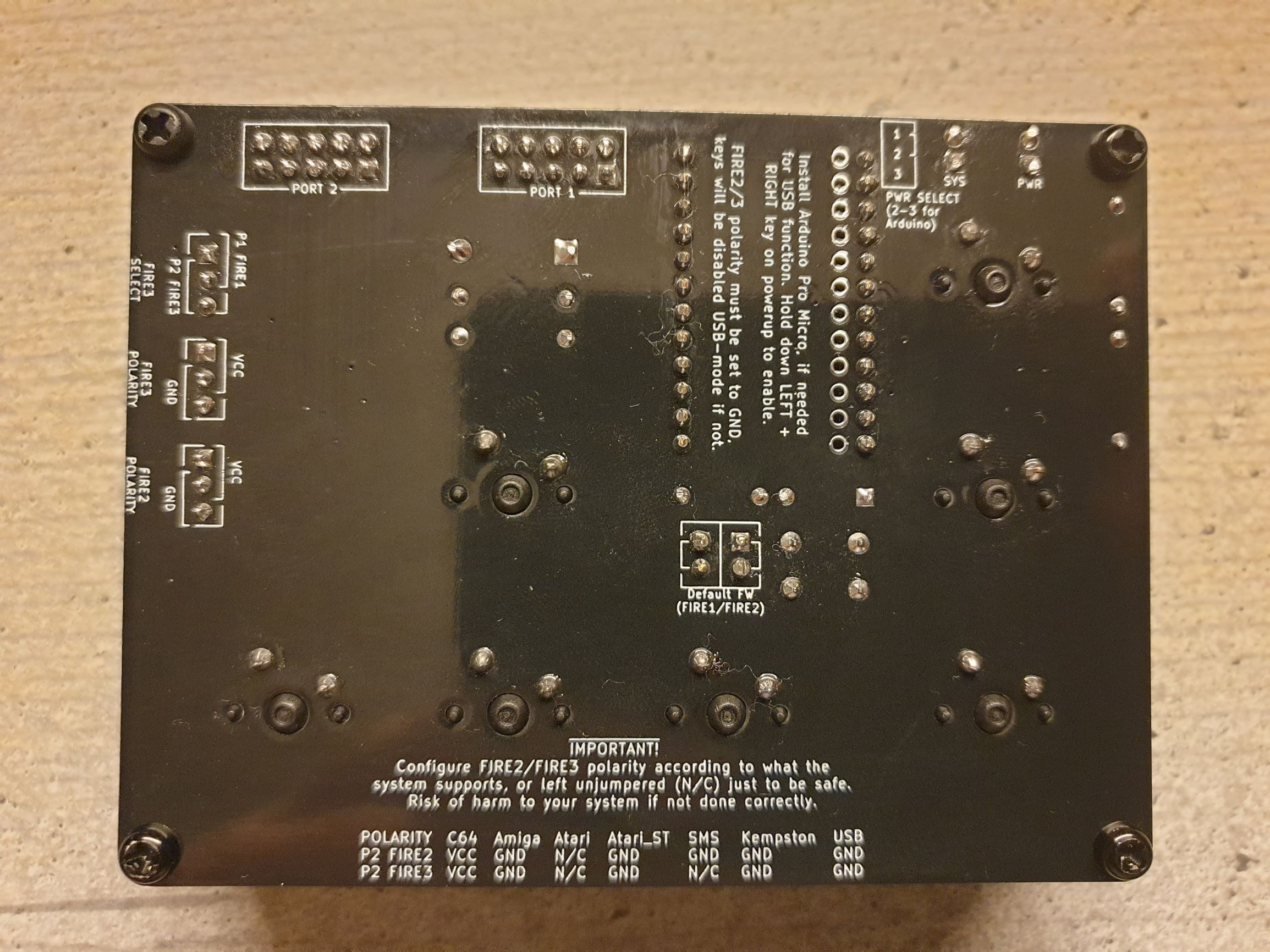
That should be most of the information you'll need. Head on over to the configuration page to ensure that you have the jumpers set up correctly before actually connecting it to something (configuration for Commodore 64 shown below). Check out the firmware page if you installed an Arduino Pro Micro and need some ready-made code for it.
This section attempts to maintain a list of the parts you'd need in order to build a feature-complete C64 JoyKEY, any parts that you could potentially do without have part counts listed in parenthesis. You will find all tested PCBs including on PCBWay shared projects relation to this project, this will also include any adapters - if you should need them. See faceplates for some more information on those.
| Reference | Item | Count | Order |
|---|---|---|---|
| PCB | Fabricate using Gerber files | 1 | PCBway |
| PCB Faceplate A1 | Fabricate using Gerber files | (1) | PCBway |
| A1 | Arduino Pro Micro | (1) | |
| 12-pin straight pin header | (2) | ||
| D1,D2 | 5mm LED | (2) | |
| D3 ** | 1N4001 diode DO-41 | (1) | |
| D4 | 1n4148 diode DO-35 | (1) | |
| D5-D11 * | 3mm or 2x3x4mm LED | (7) | |
| J1,J2 *** | 2x5 pin straight header pins or 2x5 IDC | 2 | |
| 2x5 pin IDC to female DB9 cable | 1 (1) | ||
| JP1-JP3 | 3-pin right-angle header pins | 3 | |
| Q1 * | 2N3904 (TO-92) | (1) | |
| R1,R2 | 270 ohm resistor | 2 | |
| R3,R4 | 220 ohm resistor | (2) | |
| R5,R14-R21 | 10k ohm resistor | (9) | |
| R6,R12 | 330 ohm resistor | (7) | |
| R13 | 1k ohm resistor | (1) | |
| SW1-SW7 **** | Cherry MX compatible switch (green) | 7 | |
| MX compatible 1u blank keycaps | 7 | ||
| SW8 | Tactile momentary switch 6x6x6mm | (1) | |
| 3M bumpon adhesive rubber feet | (4) | ||
| Nylon M3 hex standoffs 8mm | (4) | ||
| Nylon M3 screws | (8) |
*) These are components exclusively used by the underglow LEDs, these are there to light up the keycaps and serve no other function than looking cool. As noted below you'll need key switches with an opening for installing these, the Gateron brand switches I tested usually do. You'll need either 3mm LEDs, 2x3x4mm LEDs should also fit rather nicely.
**) Replace with piece of wire if not installing Arduino Pro Micro on the board, or you know you won't need the alternative autofire firmware at any point.
***) Breakable dual row pin headers can be used here, but I find it is nicer to use a 2x5 pin connector here instead. The easiest way to get a cable like this is to order a couple of 2x5 pin IDC cable (usually listed as AVR or JTAG cable) with sufficient length, cut off the end you don't need and then attach a female DB9 connector of the IDC variety. Pre-made cables have been observed on ebay, but have not seen any that are more than 20cm in length.
****) I've been using the cheaper Gateron clones and they work well for this type of use, you can use either the 3- or 5-pin variety. The green and blue switches are the ones that have a clicky sound, pick a different colour if that is not something you'd be interested in. If you want LEDs below the keycaps, you need switches with a spot for those like the Gateron brands do. The keycaps you need are usually listed as mechanical gaming MX-compatible keycaps.
The necessity for adapters will depend on the type of systems that you have, so I've separated the BOM for those into separate modules. See document adapters for a list of available and tested adapters, click on the ones you are interested in to get a BOM for those.
