This document reflects the current state of knowledge: It may contain errors and misassumptions.
- Protocol: Half-Duplex USART (TX and RX on a single wire)
- Baud-Rate: 9600bit/s
- Transfer-Bits: 8
- Stop-Bits: 2
The heatpumps HMI controller board is based upon a STM32F103RFT6 and provides a 8-pin (2x4 2,54mm) connector.
The original setup needs 4 of those pins, which are connected to the main controller:
- VCC 5V (green)
- GND (red/brown)
- TX/RX, Logical 5V (white)
- Unknown/Unused(yellow)
Depending on the heatpump, sometimes there are only three wires.
The protocol uses an unknown binary frame format, with each message consisting of an unique identifier, payload length, payload and checksum.
- 1 byte message identifier
- 1 byte payload Length
- 1-255 bytes payload
- 2 bytes checksum (CRC-16)
Example Messages:
ID LEN ----------------------------------------------- PAYLOAD ------------------------------------------------------------------ CRC16..
193 37 235 1 121   0 94   0 102   0 0  0   0 0 1 100  65 81  0   0   0 50 62 0 255 255 255 87  9 66 88   2   0  16  14   1 78  23 254 243
194 35  18 2  66 252  0 240  17 240 6 16  56 0 0 255 255  0 30 147  46 11 11 0   0 255   0  9 66  1  1 255 255 255 255 255         74 199
 67 31   0 0   0   0  0   0   0   0 0  0 181 9 0   0  23  0  0   0 181  9  0 0 168 195  18  0  0  0  0   0                         25  82
 74 35   0 0   0   0  0   0   0   0 0  0   0 0 0   0   0  0  0   0   0  0  0 0   0   0   0  0  0  0  0   0   0   0   0   0         18 176
There are currently no insights, why they've chosen 193, 194, 67 and 74 and if there is an additional but yet unknown meaning in these identifiers
The two byte checksum value is created using standard CRC-16/CCITT-FALSE. The checksum is created for payload length and the actual payload itself:
Example Message 67 in decimal and hexadecimal representation:

DEC: 31  0  0  0  0  0  0  0  0  0  0 181  9  0  0 23  0  0  0 181  9  0  0 168 195 18  0  0  0  0  0 25 82
HEX: 1F 00 00 00 00 00 00 00 00 00 00  B5 09 00 00 17 00 00 00  B5 09 00 00  A8  C3 12 00 00 00 00 00 19 52
In this message we expect an CRC of 0x1952 (last two bytes). Using the CRC-16/CCITT-FALSE algorithm we are able to
successfully recreate the CRC
values: See online crc result using crccalc.com
Messages are either send from the main or the hmi controller. The main controller is the master of the communication and is repeating a pattern of message identifiers. The message sequence during normal operation is:
194 (HMI)
56ms idle
67 (MAIN)
60ms idle
193 (MAIN)
150ms idle
(repeated)
If an error message is requested by the HMI controller, the sequence contains another message with identifier 74.
194 (HMI)
56ms idle
67 (MAIN)
60ms idle
193 (MAIN)
54ms idle
74 (MAIN)
56ms idle

In case we disconnect the HMI controller during operation, we will notice that the 194 frame is no longer complete:

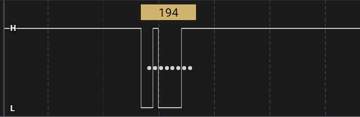
Therefore, message 194 is completed by the HMI controller, whereas 193 and 67 are emitted by the main controller.
The main controller gives the HMI controller permission to send by emitting the 194 message type on the wire. The HMI controller completes the packet on the one-wire bus.
| Byte Number | Example | Purpose/Function | Other Information |
|---|---|---|---|
| 0 | 35 | Length Field | - |
| 1 - 2 | 18 2 | Target Temp. | See Temperature Table, 53°C |
| 3 | 66 | OperationMode | See Operation Mode Table |
| 4 | 252 | Command: Change PWM, Command: Change Anti-Dry-Heating | See Commands |
| 5 | 0 | Anti-Legionella Mode / AirDuct Mode | 0 == Off, 1 == 1perMonth, 2 == 2perMonth, 3 == 3perMonth, 4 == 4/perMonth, // 0 == AirDuct INT/INT, 16 == AirDuct EXT/INT, 32 == AirDuct EXT/EXT |
| 6 | 240 | Emergency-Mode, Command: Change Connectivity | "Emergency Mode Off == 240, Emergency Mode On == 241", "Disabled Connectivity: No == 240, Disabled Connectivity: Yes == 16" |
| 7 | 17 | InstallationConfig | WP-Only == 0, WP+ExtBoiler-Prio-WP == 1, Wp+ExtBoiler-Opt-WP == 17, Wp+ExtBoiler-Opt-ExtBoiler == 33 , Wp+ExtBoiler-Prio-ExtBoiler == 49 , WP + Solar == 50 |
| 8 | 240 | ExhaustFanConfig, Command: Change Heat-Exchanger | Exhaust Fan Stop == 240, Low Speed == 241, High Speed == 242. See Commands |
| 9 | 4 | Heating-Element / SetupState / PV allowed | Heating-Element Automatic-Mode == 4, Heating-Element Disabled == 0, Setup Factory Settings == 164, Setup Airduct Set == 36, Setup Finished == 4 ... and PV allowed but not enabled = 4, PV allowed and enabled = 6 |
| 10 | 16 | Timer Mode: Window 1 Start | 16 = 04:00h, 12 = 03:00h |
| 11 | 56 | Timer Mode: Window 1 Length | 52 = 13h runtime, 56 = 14h runtime |
| 12 | 0 | Timer Mode: Window 2 Start | e.g. 52 = 13:00h - Value 0x00 0x00 is supported if Timer 2 is not set. |
| 13 | 0 | Timer Mode: Window 2 Length | e.g. 16 = 04h runtime. Max allowed length of both timers in sum is 14h runtime |
| 14 | 255 | Command: Change PV-Input, Change Circulation | - |
| 15 | 255 | Command: Change Min Target Temperature | Note: Range 40-50°C |
| 16 | 0 | Command: Clear Alarm (Error Beeps) | 0 == Noop, 4 == Clear Alarm / Errors |
| 17 | 25 | Current Time Seconds | - |
| 18 | 151 | Current Day, Current Month in Half-Year | See Formula below |
| 19 | 46 | Current Year, Half-Year | See Formula below |
| 20 | 11 | Current Time Minutes | - |
| 21 | 13 | Current Time Hour | - |
| 22 | 0 | TestMode Status | HMI Left TestMode == 0, HMI Entered TestMode == 1, Heatpump TestMode == 2, Heating-Element TestMode == 3, Fan-Slow TestMode == 4 , Fan-Fast TestMode == 5 , Defrost TestMode == 6, Heatpump + EXT Boiler TestMode == 8 |
| 23 | 0 | ? | - |
| 24 | 255 | Command: Change PWM Value, Contains PWM Setpoint | - |
| 25 | 0 | ? | - |
| 26 | 9 | ? | - |
| 27 | 66 | ? | - |
| 28 | 0 | Command: Request Error Message / Error Number | Error Number (1..x) |
| 29 | 0 | Command: Request Error Message / Request Id | Upcounting (1..255 |
| 30 | 255 | Command: Change Anti-Legionalla Temperature Target | See Commands. Note: Valid Range 62-70°C |
| 31 | 255 | Command: Change Installed Wattage Heat Element | See Commands. Note: Valid Range 10-30 (1000 - 3000W) |
| 32 | 255 | Command: Change Brand of Heat-Pump | See Commands. |
| 33 - 34 | 255 255 | Command: Change Boiler Capacity | See Commands. |
Findings...
2dec  | 0000 0010:  AlwaysOn + ECO Inactive
3dec  | 0000 0011:  AlwaysOn + Boost
64dec | 0100 0000:  TimerMode + Absence
65dec | 0100 0001:  TimerMode + ECO Active
66dec | 0100 0010:  TimerMode + ECO Inactive
67dec | 0100 0011:  TimerMode + Boost
68dec | 0100 0100:  TimerMode + AUTO
| Bit Number | Purpose/Function | Other Information |
|---|---|---|
| 0 - 3 | Operation Mode | Interpreted as integer, 0 == Absence, 1 == Eco Active, 2 == Eco Inoactive, 3 == Boost, 4 == Auto |
| 4 | ? | |
| 5 | ? | |
| 6 | TimerMode enabled | |
| 7 | ? |
Temperature values have an accuracy of a single decimal place. The two bytes are interpreted as an uint16 value and divided by 10:
float temperature = (float) (((int16_t) message[2] << 8) | message[1]) / 10.0;
Example Table:
184 1 = 44,0°C
194 1 = 45,0°C
204 1 = 46,0°C
214 1 = 47,0°C
224 1 = 48,0°C
234 1 = 49,0°C
244 1 = 50,0°C
254 1 = 51,0°C
8 2   = 52,0°C
18 2  = 53,0°C
28 2  = 54,0°C
38 2  = 55,0°C
48 2  = 56,0°C
58 2  = 57,0°C
68 2  = 58,0°C
78 2  = 59,0°C
88 2  = 60,0°C
98 2  = 61,0°C
108 2 = 62,0°C
    uint16_t year  = 2000 + (payload[19] / 2);
    uint8_t  month = (payload[18] >> 5) + ((payload[19] % 2) * 8);
    uint8_t  day   = payload[18] & 0x1F;
Example Table (Byte 19):
42dec = 2021 (First Half)
43dec	= 2021	(Second Half)
44dec	= 2022	(First Half)
45dec	= 2022	(Second Half)
46dec	= 2023	(First Half)
47dec	= 2023	(Second Half)
Commands are executed by the HMI as soon as placeholder fields/values are replaced by command values. The HMI Controller awaits the change of the Main controller and then resets the placeholder fields to the previous placeholder value.
- Affected Byte Positions: 33, 34
Examples:
Noop: 35 18 2 65 252 0 240 32 240 4 60 16 16 24 255 255 0  x x x x x 0 0 255 0 9 66 1 1 255 255 255 255 255
270l: 35 18 2 65 252 0 240 32 240 4 60 16 16 24 255 255 0  x x x x x 0 0 255 0 9 66 1 1 255 255 255  14   1
200l: 35 18 2 65 252 0 240 32 240 4 60 16 16 24 255 255 0  x x x x x 0 0 255 0 9 66 1 1 255 255 255 200   0
- Affected Byte Positions: 4, 24
- Allowed Range 50-100%
Examples:
Noop:         35 18 2 65 252 0 240 32 240 4 60 16 16 24 255 255 0  x x x x x 0 0 255 0 9 66 1 1 255 255 255 255 255
PWM 1 to 50:  35 18 2 65  60 0 240 32 240 4 60 16 16 24 255 255 0  x x x x x 0 0  50 0 9 66 1 1 255 255 255 255 255
PWM 1 to 65:  35 18 2 65  60 0 240 32 240 4 60 16 16 24 255 255 0  x x x x x 0 0  65 0 9 66 1 1 255 255 255 255 255
PWM 2 to 81:  35 18 2 65 124 0 240 32 240 4 60 16 16 24 255 255 0  x x x x x 0 0  81 0 9 66 1 1 255 255 255 255 255
PWM 2 to 60:  35 18 2 65 124 0 240 32 240 4 60 16 16 24 255 255 0  x x x x x 0 0  60 0 9 66 1 1 255 255 255 255 255
PWM 3 to 100: 35 18 2 65 188 0 240 32 240 4 60 16 16 24 255 255 0  x x x x x 0 0 100 0 9 66 1 1 255 255 255 255 255
PWM 3 to 66:  35 18 2 65 188 0 240 32 240 4 60 16 16 24 255 255 0  x x x x x 0 0  66 0 9 66 1 1 255 255 255 255 255
- Affected Byte Positions: 32
- 65dec = Atlantic
- 78dec = NoName
- 83dec = Sauter
- 84dec = Thermor
Noop:     35 18 2 65 252 0 240 32 240 4 60 16 16 24 255 255 0  x x x x x 0 0 255 0 9 66 1 1 255 255 255 255 255
Atlantic: 35 18 2 65 252 0 240 32 240 4 60 16 16 24 255 255 0  x x x x x 0 0 255 0 9 66 1 1 255 255  65 255 255
NoName:   35 18 2 65 252 0 240 32 240 4 60 16 16 24 255 255 0  x x x x x 0 0 255 0 9 66 1 1 255 255  78 255 255
Sauter:   35 18 2 65 252 0 240 32 240 4 60 16 16 24 255 255 0  x x x x x 0 0 255 0 9 66 1 1 255 255  83 255 255
Thermor:  35 18 2 65 252 0 240 32 240 4 60 16 16 24 255 255 0  x x x x x 0 0 255 0 9 66 1 1 255 255  84 255 255
- Affected Byte Positions: 8
Noop: 35 18 2 65 252 0 240 32 240 4 60 16 16 24 255 255 0  x x x x x 0 0 255 0 9 66 1 1 255 255 255 255 255
Yes:  35 18 2 65 252 0 240 32  16 4 60 16 16 24 255 255 0  x x x x x 0 0 255 0 9 66 1 1 255 255 255 255 255
No:   35 18 2 65 252 0 240 32   0 4 60 16 16 24 255 255 0  x x x x x 0 0 255 0 9 66 1 1 255 255 255 255 255
- Affected Byte Positions: 6
Noop:         35 18 2 65 252 0 240 32 240 4 60 16 16 24 255 255 0  x x x x x 0 0 255 0 9 66 1 1 255 255 255 255 255
Not Disabled: 35 18 2 65 252 0 240 32 240 4 60 16 16 24 255 255 0  x x x x x 0 0 255 0 9 66 1 1 255 255 255 255 255
Disabled:     35 18 2 65 252 0 16  32 240 4 60 16 16 24 255 255 0  x x x x x 0 0 255 0 9 66 1 1 255 255 255 255 255
- Affected Byte Positions: 14
Noop: 35 18 2 65 252 0 240 32 240 4 60 16 16 24 255 255 0  x x x x x 0 0 255 0 9 66 1 1 255 255 255 255 255
No:   35 18 2 65 252 0 240 32 240 4 60 16 16 24 240 255 0  x x x x x 0 0 255 0 9 66 1 1 255 255 255 255 255
Yes:  35 18 2 65 252 0 240 32 240 4 60 16 16 24 241 255 0 x x x x x  0 0 255 0 9 66 1 1 255 255 255 255 255
- Affected Byte Positions: 14
Noop: 35 18 2 65 252 0 240 32 240 4 60 16 16 24 255 255 0  x x x x x 0 0 255 0 9 66 1 1 255 255 255 255 255
No:   35 18 2 65 252 0 240 32 240 4 60 16 16 24  16 255 0  x x x x x 0 0 255 0 9 66 1 1 255 255 255 255 255
Yes:  35 18 2 65 252 0 240 32 240 4 60 16 16 24  17 255 0  x x x x x 0 0 255 0 9 66 1 1 255 255 255 255 255
- Affected Byte Positions: 16
- Allowed Range 40-50°C
Noop:  35 18 2 65 252 0 240 32 240 4 60 16 16 24 255 255 0  x x x x x 0 0 255 0 9 66 1 1 255 255 255 255 255
44°C:  35 18 2 65 252 0 240 32 240 4 60 16 16 24 255  44 0  x x x x x 0 0 255 0 9 66 1 1 255 255 255 255 255
40°C:  35 18 2 65 252 0 240 32 240 4 60 16 16 24 255  40 0 x x x x x  0 0 255 0 9 66 1 1 255 255 255 255 255
- Affected Byte Positions: 4
Noop:     35 18 2 65 252 0 240 32 240 4 60 16 16 24 255 255 0  x x x x x 0 0 255 0 9 66 1 1 255 255 255 255 255
Enabled:  35 18 2 65 128 0 240 32 240 4 60 16 16 24 255 255 0  x x x x x 0 0 255 0 9 66 1 1 255 255 255 255 255
Disabled: 35 18 2 65 132 0 240 32 240 4 60 16 16 24 255 255 0  x x x x x 0 0 255 0 9 66 1 1 255 255 255 255 255
- Affected Byte Positions: 30
- Range: 62-70°C
Examples:
Noop: 35 18 2 65 252 0 240 32 240 4 60 16 16 24 255 255 0  x x x x x 0 0 255 0 9 66 1 1 255 255 255 255 255
62°C: 35 18 2 65 252 0 240 32 240 4 60 16 16 24 255 255 0  x x x x x 0 0 255 0 9 66 1 1  62 255 255 255 255
70°C: 35 18 2 65 252 0 240 32 240 4 60 16 16 24 255 255 0  x x x x x 0 0 255 0 9 66 1 1  70 255 255 255 255
- Affected Byte Positions: 31
- Range 1000 - 3000W
- Value divided by 100
Noop:  35 18 2 65 252 0 240 32 240 4 60 16 16 24 255 255 0  x x x x x 0 0 255 0 9 66 1 1 255 255 255 255 255
1000W: 35 18 2 65 252 0 240 32 240 4 60 16 16 24 255 255 0  x x x x x 0 0 255 0 9 66 1 1 255  10 255 255 255
1600W: 35 18 2 65 252 0 240 32 240 4 60 16 16 24 255 255 0  x x x x x 0 0 255 0 9 66 1 1 255  16 255 255 255
1700W: 35 18 2 65 252 0 240 32 240 4 60 16 16 24 255 255 0  x x x x x 0 0 255 0 9 66 1 1 255  17 255 255 255
3000W: 35 18 2 65 252 0 240 32 240 4 60 16 16 24 255 255 0  x x x x x 0 0 255 0 9 66 1 1 255  30 255 255 255
If an error occurred which is recoverable, the hmi offers the functionality to "stop the alarm". This will resume the operation of the heatpump and clears the error.
- Affected Byte Position: 16
Noop:         35 18 2 65 252 0 240 32 240 4 60 16 16 24 255 255 0  x x x x x 0 0 255 0 9 66 1 1 255 255 255 255 255
Clear Alarm:  35 18 2 65 252 0 240 32 240 4 60 16 16 24 255 255 4  x x x x x 0 0 255 0 9 66 1 1 255 255 255 255 255
- Affected Byte Positions: 27 - 28
- Triggers the main controller to emit a single message 74 (error message)
- RequestId is incremented for each request, starting from zero, most likely with wrap around.
- The error number addresses the list of errors, the most recent error is id==1
- If an error number is addressed which is not existent, the main controller will respond with an empty error message ( zeroed)
Noop:                                     35 18 2 65 252 0 240 32 240 6 60 16 16 24 255 255 0 x x x x x 0 0 255 0 9 66 0  0 255 255 255 255 255
Request Error No 1 with Request Id: 76    35 18 2 65 252 0 240 32 240 6 60 16 16 24 255 255 0 x x x x x 0 0 255 0 9 66 1 76 255 255 255 255 255
Request Error No 2 with Request Id: 77    35 18 2 65 252 0 240 32 240 6 60 16 16 24 255 255 0 x x x x x 0 0 255 0 9 66 2 77 255 255 255 255 255
| Byte Number | Example | Purpose/Function | Other Information |
|---|---|---|---|
| 0 | 37 | Length Field | - |
| 1 - 2 | 235 1 | Hot Water Temp. | Note: Range Allowed 18 - 62°C |
| 3 - 4 | 121 0 | Input Air Temp | Note: Range Allowed 10 - 27°C |
| 5 - 6 | 94 0 | Lower Evaporator Temp | Note: Range Allowed -2 - 41°C |
| 7 - 8 | 102 0 | Upper Evaporator Temp | Note: Range Allowed -3 - 39°C |
| 9 | 0 | ? | - |
| 10 | 0 | ? | - |
| 11 | 0 | ? | - |
| 12 | 0 | ? | - |
| 13 | 1 | ? | - |
| 14 | 100 | Setting: PWM Level 3 | Note: Range Allowed in HMI 50-100%, Adjustable from HMI controller |
| 15 | 65 | Setting: PWM Level 1 | Note: Range Allowed in HMI 50-100%, Adjustable from HMI controller |
| 16 | 81 | Setting: PWM Level 2 | Note: Range Allowed in HMI 50-100%, Adjustable from HMI controller |
| 17 | 8 or 0 | Picture Bitmask | See table below |
| 18 - 19 | 0 0 | Fan-Speed | Either 0 (off) or 650 (lowspeed) or 810 (highspeed) Maybe rpm? Does this reflect the PWM settings? |
| 20 | 44 | Setting: Min T Target | Adjustable from HMI controller |
| 21 | 62 | Setting: Anti-Legionella T Target | Adjustable from HMI controller |
| 22 | 0 | State: PV and Solar Input | 16 == PV Enabled and Active, 32 == Solar Input Triggered |
| 23 | 255 | Error-Code | In Error State this contains Error Code, eg. 7 |
| 24 | 255 | Error-Code | In Error State this contains 0 |
| 25 | 255 | Error-Code | In Error State this contains 0 |
| 26 | 87 | ? | - |
| 27 | 9 | ? | - |
| 28 | 66 | ? | - |
| 29 | 88 | ? | - |
| 30 | 2 | ? | - |
| 31 | 0 | ? | - |
| 32 | 16 | Setting: Wattage Heat-Element | Note: Multiplied by 100 -> 1600W, Adjustable from HMI controller |
| 33 - 34 | 14 1 | Setting: Boiler Capacity (l) | '14 1' == 270l, '200 0' == 200l, Adjustable from HMI controller |
| 35 | 78 | Setting: Brand | 65 == Atlantic, 78 == NoName, 83 == Sauter, 84 == Thermor, Adjustable from HMI controller |
| 36 | 21 | Setting: Bitflags | See Table below, Adjustable from HMI controller |
Findings...
0dec   | 0000 0000: Nothing Shown on HMI
8dec   | 0000 1000: Fan is turned on (observed via testmode)
9dec   | 0000 1001: Heating Element
10dec  | 0000 1010: Heatpump
11dec  | 0000 1011: Heatpump + Heating Element
14dec  | 0000 1110: Heatpump + Boiler Backup
15dec  | 0000 1111: Heatpump + Heating Element + Boiler Backup
32dec  | 0010 0000: Defrost
34dec  | 0010 0010: Defrost + Heatpump
40dec  | 0010 1000: Defrost + Fan
41dec  | 0010 1001: Defrost + Fan + Heating Element
64dec  | 0100 0000: Unknown, Observed while triggering Error 7
192dec | 1100 0000: Unknown, Observed while triggering Error 7
| Bit Number | Purpose/Function | Other Information |
|---|---|---|
| 0 | Heating Element On/Off | |
| 1 | Heatpump On/Off | |
| 2 | Boiler Backup On/Off | |
| 3 | Fan On/Off. | |
| 4 | ? | |
| 5 | Defrost On/Off | |
| 6 | ? | |
| 7 | ? |
Findings...
5dec  | 0000 0101: Communication Enabled, PV enabled, No Circulation, Anti-Dry-Heating
17dec | 0001 0001: Communication Enabled, PV disabled, Heat-Exchanger available, No Circulation, No Anti-Dry-Heating
20dec | 0001 0100: Communication Enabled, PV enabled, Heat Exchanger not available, No Circulation, No Anti-Dry-Heating
21dec | 0001 0101: Communication Enabled, PV enabled, No Circulation, No Anti-Dry-Heating
23dec | 0001 0111: Communication Enabled, PV enabled, With Circulation Enabled, No Anti-Dry-Heating
29dec | 0001 1101: Communication Disabled, PV enabled, Heat-Exchanger available, No Circulation, No Anti-Dry-Heating
| Bit Number | Purpose/Function | Other Information |
|---|---|---|
| 0 | Heat-Exchanger Available | |
| 1 | Circulation Enabled | |
| 2 | PV Input Enabled | If flag is set, pv input is enabled |
| 3 | Communication Disabled | If flag is set, io-homecontrol/cozytouch is disabled |
| 4 | Anti-Dry-Heating Disabled | If flag is set, there is no Anti-Dry-Heating |
| 5 | ? / Unused | |
| 6 | ? / Unused | |
| 7 | ? / Unused |
| Byte Number | Example | Purpose/Function | Other Information |
|---|---|---|---|
| 0 | 31 | Length Field | - |
| 1 - 2 | 221 1 | Power Consumption Heatpump | - |
| 3 - 4 | 0 0 | Power Consumption Heating Element | - |
| 5 | 0 | ? | - |
| 6 | 0 | ? | - |
| 7 - 8 | 221 1 | Power Consumption Total (Both) | - |
| 9 - 10 | 54 215 | Total Water Production (l) | Ticket |
| 11 - 14 | 231 9 0 0 | Total Operation Hours (Heatpump) | - |
| 15 - 18 | 24 0 0 0 | Total Operation Hours (Heating Element) | - |
| 19 - 22 | 231 9 0 0 | Total Operation Hours (Both) | - |
| 23 - 30 | 127 37 19 0 0 0 0 0 | Total Energy Counter (Wh) | - |
Error messages are emitted by the main controller if the HMI is requesting error messages.
- Any change to byte 27 and byte 28 of the HMI (194) message will trigger a new error message.
- The main controller is emitting empty error messages if HMI is requesting placeholder values (errorNumber==0, requestId==0) or if an invalid errorNumber has been requested.
- Entering Secret Diagnosis Menu: HMI will fetch all existing errors
- The HMI controller will request an error message if the error bitflag (within main message, byte 17) has been set.
- The MAIN controller will never emit an error message, without an HMI controller asking for it.
- ErrorID == 0 is reserved and always contains an empty error message if requested.
| Byte Number | Example | Purpose/Function | Other Information |
|---|---|---|---|
| 0 | 35 | Length Field | - |
| 1 | 3 | Request-Id | Matches original request from HMI |
| 2 | 7 | Error-Code | - |
| 3 | 0 | ? | - |
| 4 - 5 | 62 2 | Water-Temperature | - |
| 6 - 7 | 213 0 | Air-Temperature | - |
| 8 - 9 | 212 0 | Upper Evaporator | - |
| 10 - 11 | 206 0 | Lower Evaporator | - |
| 12 | 0 | ? | - |
| 13 | 0 | ? | - |
| 14 | 0 | ? | - |
| 15 | 0 | ? | - |
| 16 | 0 | State Flags | 6 == HeatPump Active + Fan (?) |
| 17 | 0 | ? | - |
| 18 | 0 | ? | - |
| 19 | 0 | ? | - |
| 20 | 0 | ? | - |
| 21 | 0 | Fan-Speed PWM | - |
| 22 | 0 | ? | - |
| 23 | 0 | ? | - |
| 24 | 0 | ? | - |
| 25 | 252 | Runtime Heat-Element | - |
| 26 | 0 | Runtime Heat-Element | - |
| 27 | 146 | Runtime Heat-Pump | - |
| 28 | 19 | Runtime Heat-Pump | - |
| 29 | 185 | Date | - |
| 30 | 48 | Date | - |
| 31 | 29 | Time: Minutes | - |
| 32 | 21 | Time: Hours | - |
| 33 | 1 | Operation Mode | 0 == Absence, 1 == Eco/Manuell EC ... |
| 34 | 4 | ? | - |