Version: 1.0 Date: 2020-12-21
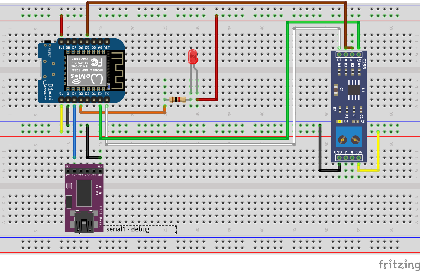
This sketch is useful for debugging and testing RS485/UART wirings. Often the remote device is mounted somewhere on a rooftop or another inconvenient place. That's where this tool comes in and offers you a simulation for your lab.
It was intentionally made for the wind direction sensor: https://github.com/AndreasExner/iobroker-IoT-WindSensor
But it can be used for different purposes as well.
#define SERIAL_BAUD_RATE 9600 //baud rate for RS485
#define DEBUG_BAUD_RATE 115200 //baud rate for FT232 / serial1

int counter=0;
bool debug = true;


byte windSensorFrame[] = {0x01, 0x03, 0x04, 0x00, 0x5A, 0x00, 0x00, 0x00, 0x00}; // default answer frame for the wind sensor DO NOT CHANGE
byte customFrame[] = {0x01, 0x00, 0x00, 0x00, 0x00, 0x00, 0x00, 0x00, 0x00}; // your custom answer frame (CRC will be calculated automatically)

bool useWindSensorFrame = true; // echos a random wind direction if true, a custom frame or a copy of the incoming frame if false
bool useCustomFrame = false; // echos the custom frame if true, a copy of the incoming frame if false

int expectedFrameSize = 8; // expected RX frame size
Do not activate useWindSensorFrame and useCustomFrame at the same time or the code will fail! Deactivate both to echo the RX frame back to the sender.
- Software
- Arduino IDE 1.8.13 (Windows)
- EspSoftwareSerial 6.10.0 plerup/espsoftwareserial: Implementation of the Arduino software serial for ESP8266 (github.com)
- Hardware
- NodeMCU Lolin V3 (ESP8266MOD 12-F)
- NodeMCU D1 Mini (ESP8266MOD 12-F)
- 5 V MAX485 / RS485 Modul TTL to RS-485 MCU
- FT232 Module
