-
Notifications
You must be signed in to change notification settings - Fork 168
Viking_Orbiter_Mission
Viking Orbiter Mission 
Brief Mission Summary 
NASA's Viking Mission to Mars was composed of two spacecraft, Viking 1 and Viking 2, each consisting of an orbiter and a lander. The primary mission objectives were to obtain high resolution images of the Martian surface, characterize the structure and composition of the atmosphere and surface, and search for evidence of life.
Viking 1 was launched on August 20, 1975 and arrived at Mars on June 19, 1976. The first month of orbit was devoted to imaging the surface to find appropriate landing sites for the Viking Landers. On July 20, 1976 the Viking 1 Lander separated from the Orbiter and touched down at Chryse Planitia.
Viking 2 was launched September 9, 1975 and entered Mars orbit on August 7, 1976. The Viking 2 Lander touched down at Utopia Planitia on September 3, 1976.
Science Goals 
The Orbiters imaged the entire surface of Mars at a resolution of 150 to 300 meters, and selected areas at 8 meters. The Viking 2 Orbiter was powered down on July 25, 1978 after 706 orbits, and the Viking 1 Orbiter on August 17, 1980, after over 1400 orbits.
Science Instruments 
The Viking Visual Imaging Subsystem (VIS) on the orbiter consisted of twin high-resolution, slow-scan television framing cameras mounted on the scan platform of each orbiter with the optical axes offset by 1.38 deg. Each of the two identical cameras on each orbiter had mechanical shutters; a 475-mm focal length telescope; a 37-mm diameter vidicon (video camera tube), the central section of which was scanned in a raster (i.e. image) format of 1056 lines by 1182 samples.
A filter wheel between the lens and shutter held six color filter positions: blue (0.35 to 0.53 micrometers), minus-blue (0.48 - 0.70), violet (0.35 - 0.47), green (0.50 - 0.60), red (0.55
- 0.70), and clear (no filter). The footprint of each image covers roughly 40 x 44 km, acquired from an altitude of 1500 km. The configuration of the cameras provided overlapping, wide-swath coverage of the surface. Each pixel was digitized as a 7-bit number (0 to 127) stored in the onboard tape-recorder, and later transmitted to Earth and converted to an 8-bit number by multiplying by 2.
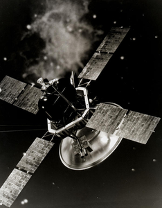
Viking Oribiter Artist's concept drawing (NASA, 1973, KSC-73PC-0648)
Viking 1 Orbiter image of Central Tithonium Chasma,
Mars Landslide lobes can be seen on the 6 km deep
canyon floor. Some layering is visible on the south
wall. The image is ~90 km across. North is at ~11:30.
(Viking Orbiter 064A22, image & caption credit: NASA)
References & Related Resources 
Viking Orbiter Mission and Instrument 
Viking Orbiters 
Planetary Data System (PDS) Information and Data Search Tools 
- PDS Imaging Node:
- PDS Geosciences Node:
- PDS Engineering Node:
- PDS Navigation and Ancillary Information Node:
Viking1_Tithonium_Chasma_Mars.png View (254 KB) Curtis Rose, 2016-05-31 03:38 PM
VikingOrbiter_ArtistConcept.png View (379 KB) Curtis Rose, 2016-05-31 03:38 PM
- Building
- Writing Tests
- Test Data
- Start Contributing
- Public Release Process
- Continuous Integration
- Updating Application Documentation
- Deprecating Functionality
- LTS Release Process and Support
- RFC1 - Documentation Delivery
- RFC2 - ISIS3 Release Policy
- RFC3 - SPICE Modularization
- RFC3 - Impact on Application Users
- RFC4 - Migration of ISIS Data to GitHub - Updated Information 2020-03-16
- RFC5 - Remove old LRO LOLA/GRAIL SPK files
- RFC6 - BLOB Redesign
- Introduction to ISIS
- Locating and Ingesting Image Data
- ISIS Cube Format
- Understanding Bit Types
- Core Base and Multiplier
- Special Pixels
- FAQ

