-
Download this repo
-
install Python dependencies [add needed deps]
pip install protobuf
-
Flash the µC with the newest release [see this link] (doc/flash_stm32_fimware.md)
-
Connect µC and PC directly via Lan (or over an switch with DHCP anabled to 192.168.2.x Subnet)
-
In case you are working behind a firewall, set an exception for incoming UDP packets from the IP address of the Smartup Unit on port 7654.
-
Set ip Adress of pc to 192.168.0.200
-
Power on µC Board
-
Observe Display and LEDS see Picture
-
Start Python Interpreter and run /tools/MET4FOFDataReceiver.py
-
Start data Receiver node with:
DR=DataReceiver("192.168.0.200",7654)
If every thing works correctly you will see that a new sensor is found
Data receiver now running wating for packets
FOUND NEW SENSOR WITH ID=hex0x37300000==>dec:925892608
Attach your callback function to Sensor
DR.AllSensors[925892608].SetCallback(DumpDataMPU9250)The software was and is created with SW4STM32 (gcc). SEGGER Systemview can be used for debugging.
| Used for | Library Name | Version | Link |
|---|---|---|---|
| real-time operating system | FreeRTOS | 9.0.0 | https://www.freertos.org/FreeRTOS-V9.html |
| Ethernet | LWIP | 2.0.3 | ST DM00103685 |
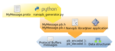
| Data serialization | nanopb | a2db482... | https://github.com/nanopb/nanopb |
see also https://jpa.kapsi.fi/nanopb/docs/ and https://github.com/nanopb/nanopb/blob/master/docs/concepts.rst
cd nanopb/
mkdir messages
cp ../protobuff_deps/messages.proto messages/
cp generator/proto/nanopb.proto ./
protoc -I=generator/proto -I=messages -I=. --proto_path=generator/proto/google/protobuf --proto_path=generator/proto/nanopb --proto_path=generator/proto -o message.pb messages/messages.proto
python generator/nanopb_generator.py message.pb
cp message.* ../protobuff_deps/
cd ./generator/proto
make
https://developers.google.com/protocol-buffers/docs/pythontutorial
cd nanopb/
mkdir ../protobuff_deps/python
protoc -I=generator/proto -I=messages -I=. --proto_path=generator/proto/google/protobuf --proto_path=generator/proto/nanopb --proto_path=generator/proto --python_out=../protobuff_deps/python/  messages/messages.proto
https://www.segger.com/products/debug-probes/j-link/models/other-j-links/st-link-on-board/ Download software extract and run STLinkReflash.exe
- Accept Segger license
- Accept ST license
- Choose Upgrade to J-Link [1] The device is flashed and reconnected Output looks like
Preparing for FW update (can take up to 10 seconds)...O.K.
Identifying ST-LINK variant...O.K.: ST-LINK/V2-1
Performing firmware update...O.K.
now you have an working J-Link at your STM32-Board.
https://www.segger.com/products/debug-probes/j-link/technology/about-real-time-transfer/
https://mcuoneclipse.com/2015/07/07/using-segger-real-time-terminal-rtt-with-eclipse/
| Param | Value |
|---|---|
| Host | 127.0.0.1 |
| Timeout | 20 sec |
| Port | 19021 |

