bladeRF CLI Tips and Tricks
Samples received via the bladeRF-cli, in either CSV or binary format, can easily be imported into tools such as Octave, MATLAB or baudline.
The first step is to open the device and configure it using the bladeRF-cli. The below example configures the device to tune to 1.575.42 MHz, with an 8MHz sample rate and 5 MHz bandwidth. Change these and the gain values as needed.
$ bladeRF-cli -i
bladeRF> set frequency rx 1575.42M

  Set RX frequency: 1575420000Hz

bladeRF> set samplerate rx 8M

  Setting RX sample rate - req:   8000000 0/1Hz, actual:   8000000 0/1Hz

bladeRF> set bandwidth rx 5M

  Set RX bandwidth - req:  5000000 Hz actual:  5000000 Hz

# Automatic gain control is enabled by default with libbladeRF 2.0.0 and later.
# If you wish to disable it and set gains manually:
#
# bladeRF> set agc off
#
# Before libbladeRF 2.0.0, 'set lnagain', 'set rxvga1', and 'set rxvga2' were
# used to individually set the gain stages on the bladeRF x40/x115. With
# libbladeRF 2.0.0 and later, on any bladeRF, 'set gain rx 60' will set maximum
# gain, and values less than 60 will be less than that:
#
# bladeRF> set gain rx 60

bladeRF> print

  RX Bandwidth:   5000000 Hz
  TX Bandwidth:  28000000 Hz

  RX Frequency: 1575420000 Hz
  TX Frequency: 1000000000 Hz

  GPIO: 0x00000037
    LMS Enable:         Enabled
    LMS RX Enable:      Enabled
    LMS TX Enable:      Enabled
    TX Band:            Low Band (300M - 1.5GHz)
    RX Band:            High Band (1.5GHz - 3.8GHz)
    RX Source:          LMS6002D

  Loopback mode: none

  RXLNA Gain:    6 dB
  RXVGA1 Gain:  30 dB
  RXVGA2 Gain:   9 dB
  TXVGA1 Gain: -14 dB
  TXVGA2 Gain:   0 dB

  Sampling: Internal

  RX sample rate: 8000000 0/1
  TX sample rate: 12000000 0/1

  Current VCTCXO trim: 0x9130
  Stored VCTCXO trim:  0x9130

  Expansion GPIO: 0xf9ff391f
  Expansion GPIO direction: 0x00000000 (1=output, 0=input)
Next, we receive samples and write them to a file.
When writing large number of samples, especially at higher sample rates, you should use the binary format to save on disk space. Additionally, consider saving samples to a ramdisk or SSD, rather than an HDD.
Below is an example of receiving (20 * 1024 * 1024) samples, using the binary "SC16 Q11" format:
bladeRF> rx config file=my_samples.sc16q11 format=bin n=20M
bladeRF> rx start;
bladeRF> rx

  State: Running
  Last error: None
  File: my_samples.sc16q11
  File format: SC16 Q11, Binary
  # Samples: 20971520
  # Buffers: 32
  # Samples per buffer: 32768
  # Transfers: 16
  Timeout (ms): 1000

bladeRF> rx wait
bladeRF> rx

  State: Idle
  Last error: None
  File: my_samples.sc16q11
  File format: SC16 Q11, Binary
  # Samples: 20971520
  # Buffers: 32
  # Samples per buffer: 32768
  # Transfers: 16
  Timeout (ms): 1000
If you'd like to save samples to a CSV, you can change the format option:
bladeRF> rx config file=my_samples.csv format=csv n=20M
bladeRF> rx start
bladeRF> rx

  State: Running
  Last error: None
  File: my_samples.csv
  File format: SC16 Q11, CSV
  # Samples: 20971520
  # Buffers: 32
  # Samples per buffer: 32768
  # Transfers: 16
  Timeout (ms): 1000

bladeRF> rx wait
bladeRF> rx

  State: Idle
  Last error: None
  File: my_samples.csv
  File format: SC16 Q11, CSV
  # Samples: 20971520
  # Buffers: 32
  # Samples per buffer: 32768
  # Transfers: 16
Timeout (ms): 1000Routines for loading/saving samples from/to various formats are provided here in the bladeRF git repository.
The below examples show how to plot the magnitude of samples received in the above example.
In the CSV format, samples are stored in rows of: I, Q.
To load these samples and reconstruct the complex signal:
% We must first tell MATLAB/Octave where to find our functions
% by pointing it to the directory containing the conversion routines.
% You will need to change this path as needed.
addpath('~/projects/bladeRF/host/misc/matlab/')

% Load the samples
signal = load_csv('my_samples.csv');

% Plot the magnitude of the signal in the time domain
plot(abs(signal));
Binary data in the SC16Q11 format is little-endian, sign-extended, and right-aligned. To load the samples and reconstruct the complex signal:
% We must first tell MATLAB/Octave where to find our functions
% by pointing it to the directory containing the conversion routines.
% You will need to change this path as needed.
addpath('~/projects/bladeRF/host/misc/matlab/')

% Load the samples
signal = load_sc16q11('my_samples.sc16q11');

% Plot the magnitude of the signal in the time domain
plot(abs(signal));
Samples must be in a binary format to be used with baudline. This section assumes you've saved them to the binary SC16Q11 format, but other conversions are certainly possible.
Here's one way to view binary samples you've saved off using the bladeRF-cli program. Note that you can open a file using these settings from the command-line as well.
- Open baudline
- Right-click and select Input -> Open File
- Change File Format to raw
- Select your file and click Open
- Set the following parameters in the raw parameters dialog:
- Decompression: OFF
- Initial byte offset: 0
- Sample Rate: Sample rate you recorded the samples at
- Channel: 2, quadrature
- Decode Format: 16 bit linear, little endian
When getting your bearings in the bladeRF-cli, it's handy to be able to visualize data while you're dialing in settings. Having external program show the samples RX'd by the bladeRF-cli comes in quite handy.
$ mkfifo /tmp/rx_samples.bin
Be sure to adjust samplerate and frequency parameters appropriately to ensure the display matches your hardware settings.
./baudline -reset -format le16 -channels 2 -quadrature -samplerate 2000000 -stdin < /tmp/rx_samples.bin
This flowgraph (python) converts bladeRF SC16 Q11 samples to GNU radio complex values and displays them with a Qt GUI sink. Note that the same conversion approach can be taken for transmitting.
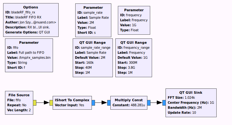
./bladeRF_fifo_rx.py --sample-rate=2e6 --frequency=433.92e6
bladeRF> set frequency 433.92M
bladeRF> set samplerate 2M
bladeRF> set bandwidth 1.5M
bladeRF> rx config file=/tmp/rx_samples.bin n=0
bladeRF> rx start
bladeRF> # Adjust parameters while viewing the spectrum in baudline!
bladeRF> rx stop
The bladeRF-cli provides the ability to transmit samples from either a binary or CSV SC16 Q11 file. It is generally very helpful during development/debugging stages to generate and write samples to a file, using one's language of choice, and then transmit them via the bladeRF-cli.
Run help tx from the CLI for a description of available parameters and other important notes.
This example shows how to use Octave or MATLAB to create samples for a simple sinusoids at +250 Khz, sampled at 2 Msps, and then transmit these sample with the bladeRF-cli. The same procedure here can be followed for your language of choice, provided you implement a few simple conversion routines.
Octave/MATLAB functions for loading/saving samples from/to the bladeRF SC16 Q11 binary and CSV formats are provided here in the bladeRF repository.
You can add these functions to your Octave/MATLAB path as follows:
>> addpath('~/projects/bladeRF/host/misc/matlab/');

help save_sc16q11
  save_sc16q11 Write a normalized complex signal to a binary file in the
    bladeRF "SC16 Q11" format.

    [RET] = save_sc16q11(FILENAME, SIGNAL)

    RET is 1 on success, and 0 on failure.

    FILENAME is the target filename. The file will be overwritten if it
    already exists. The file data is written in little-endian format.

    SIGNAL is a complex signal with the real and imaginary components
    within the range [-1.0, 1.0).
Next, we create the signal:
% Our samples must be generated at the samplerate we plan to run the device at
SAMPLE_RATE = 2e6;
% Generate 10 seconds worth of samples. Bear in mind that when using the
% binary SC16 Q11 format, 1 sample consumes 4 bytes of memory/disk space.
% This quickly adds up - 10 seconds @ 2 Msps yields ~ 76.3 MiB. Be careful
% when using higher sample rates!
NUM_SECONDS = 10;
NUM_SAMPLES = NUM_SECONDS * SAMPLE_RATE;
% 250 kHz, in radians (ω = F_Hz * 2pi)
SIGNAL_FREQ_RAD = 250e3 * 2 * pi;
% Generate a vector "t" which represents time, in units of samples.
% This starts at t=0, and creates NUM_SAMPLES samples in steps of 1/SAMPLE_RATE
t = [ 0 : (1/SAMPLE_RATE) : (NUM_SECONDS - 1/SAMPLE_RATE) ];
% Create a sinusoid (signal = e^(jωt) ) with a magnitude of 0.90
signal = 0.90 * exp(1j * SIGNAL_FREQ_RAD * t);
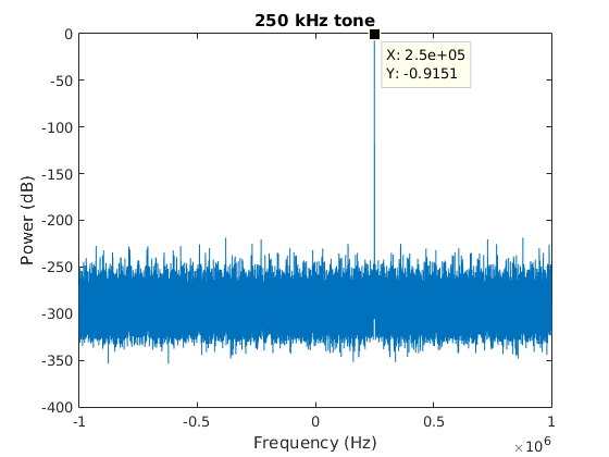
% Plot the FFT of our signal as a quick sanity check.
% The NUM_SAMPLES denominator is just to normalize this for display purposes.
f = linspace(-0.5 * SAMPLE_RATE, 0.5 * SAMPLE_RATE, length(signal));
plot(f, 20*log10(abs(fftshift(fft(signal)))/NUM_SAMPLES));
xlabel('Frequency (Hz)');
ylabel('Power (dB)');
title('250 kHz tone');
% Save the signal to a file
save_sc16q11('/tmp/samples.sc16q11', signal); Here's an example of the expected plot:
It's generally recommended to save files to /tmp or a ramdisk location, rather than to a hard disk. For higher sample rates, reading samples from disk may cause underruns.
Next, we'll enter the bladeRF command line interface:
$ bladeRF-cli -i
bladeRF>
First, we configure the device. Ensure the sample rate matches the rate the rate you created your samples with!
Note that the TXVGA1 and TXVGA2 gain values are dependent upon you're operating environment. You should start with setting these to low (e.g., TXVGA=1-20, TXVGA2=0) values if you're connecting directly to test equipment.
bladeRF> set frequency tx 925M

  Set TX frequency:  925000000Hz

bladeRF> set samplerate tx 2M

  Setting TX sample rate - req:   2000000 0/1Hz, actual:   2000000 0/1Hz

bladeRF> set bandwidth tx 1.5M

  Set TX bandwidth - req:  1500000Hz actual:  1500000Hz

bladeRF> set txvga1 -10
bladeRF> set txvga2 0


bladeRF> set bandwidth tx 1.5M

  Set TX bandwidth - req:  1500000Hz actual:  1500000Hz

bladeRF> set txvga1 -10
bladeRF> set txvga2 0
Next, we configure the CLI to transmit out samples:
bladeRF> tx config file=/tmp/samples.sc16q11 format=binYou can also repeat the transmission of a file. For example, if you'd like to repeat the file the file 3 times, with a 1 second delay between each repetition:
bladeRF> tx config repeat=3 delay=1000000Now we'll transmit the file, and observe that it is running:
bladeRF> tx start
bladeRF> tx

  State: Running
  Last error: None
  File: /tmp/samples.sc16q11
  File format: SC16 Q11, Binary
  Repetitions: 3
  Repetition delay: 1000000 us
  # Buffers: 32
  # Samples per buffer: 32768
  # Transfers: 16
  Timeout (ms): 1000
We can wait for the transmission to complete, via the tx wait command. This command will block until either the transmission completes or a specified timeout occurs. You can also interrupt this command with Ctrl-C.
bladeRF> tx wait
bladeRF> tx

  State: Idle
  Last error: None
  File: /tmp/samples.sc16q11
  File format: SC16 Q11, Binary
  Repetitions: 3
  Repetition delay: 1000000 us
  # Buffers: 32
  # Samples per buffer: 32768
  # Transfers: 16
  Timeout (ms): 1000
The following screenshot from a VSA shows this tone being transmitted at the desired 250 kHz offset from the center frequency (925MHz). Note that this is from a device with its DC offset and IQ imbalance compensated for. See wiki page describing correction features if you see significant LO leakage at the center frequency, or a significant image at -250 kHz.

Currently, the following information is stored in a user-modifiable "calibration region":
- FPGA size (40 or 115)
- VCTCXO (Voltage-controlled temperature-compensated oscillator) trim DAC value
Unless you're planning to replace the FPGA (not a recommended endeavor), there's no reason to mess with this field. The reason the FPGA size is here rather than in the OTP region is largely historic and pertains to debug usage during early development and testing.
The VCTCXO frequency will drift over time and due to environmental factors. Users will generally want to periodically recalibrate the associated trim DAC value, and write it back to the bladeRF.
From with the bladeRF-cli's interactive mode, the current calibration values can be viewed via the info command:
bladeRF> info
  Serial #:                 00000000000000000000000000000000
  VCTCXO DAC calibration:   0xa0a8
  FPGA size:                40 KLE
  FPGA loaded:              no
  USB bus:                  4
  USB address:              2
  USB speed:                SuperSpeed
  Backend:                  libusb
  Instance:                 0
Note the VCTXCO (trim) DAC calibration value above.
To back up this information to a file, which may later be restored through the bladeRF-cli program, the flash_backup command may be used. Type help flash_backup to see the full help text for this command.
The general usage for saving calibration data is flash_backup <output_file> cal:
bladeRF> flash_backup /home/jon/bladeRF-files/bladerf_cal_2014_03_18.bin cal
[INFO] Reading 0x00000100 bytes from address 0x00030000.
This command will store the calibration data, along with some additional metadata, in the specified file. To view the associated metadata stored in the flash image, use the flash_image command. This metadata may prove useful if you've accidentally renamed a file, or forgot which device (via serial number) is associated with the file.
bladeRF> flash_image /home/jon/bladeRF-files/bladerf_cal_2014_03_18.bin

Checksum: d3ad936733b841cd10f0cb852d2a133e08cf080a60c4a607cca9908b75bd5e59
Image format version: 0.1.0
Timestamp: 2014-03-18 20:25:37
Serial #: 00000000000000000000000000000000
Image type: Calibration data
Address: 0x00030000
Length:  0x00000100
If you've backed up calibration data to a file via the flash_backup command, you can use the flash_restore command to write this data back to the device. Note that the serial number information in the metadata is strictly for informational purposes; it is not used to prevent data from being written to another device.
For more information about the flash_restore command, run help flash_restore.
bladeRF> flash_restore /home/jon/bladeRF-files/bladerf_cal_2014_03_18.bin
[INFO] Reading 0x00010000 bytes from address 0x00030000.
[INFO] Erasing 0x00010000 bytes starting at address 0x00030000.
[INFO] Writing 0x00010000 bytes to address 0x00030000.
Note: A power cycle will be required for this change to take effect.
This approach useful if you'd like to manually specify a VCTCXO trim value to store in the device.
The flash_init_cal command generates a calibration region of flash, and can either write it directly to a device, or to a file (for future use with the flash_restore command).
For more information about this command, run help flash_init_cal from the bladeRF-cli interactive mode.
For a bladeRF with a 40 kLE FPGA and a desired VCTCXO trim DAC value of 0x9015, you can write this information directly to the device via:
bladeRF> flash_init_cal 40 0x9015
[INFO] Reading 0x00010000 bytes from address 0x00030000.
[INFO] Erasing 0x00010000 bytes starting at address 0x00030000.
[INFO] Writing 0x00010000 bytes to address 0x00030000.
Note: A power cycle will be required for this change to take effect.
Alternatively, to write this data to a file:
bladeRF> flash_init_cal 40 0x9015 /tmp/new_cal_data.bin
If you've managed to wipe your calibration region and do not have the necessary tools to identify an appropriate VCTCXO trim value, you may look up that factory default on this page.
bladeRF-cli -p returns 0 if one or more devices are detected, and a non-zero value if no devices are connected. Below is a snippet you can use to exit a script if no bladeRF devices are detected:
#!/bin/sh

bladeRF-cli -p 1>/dev/null 2>&1
if [ $? -ne 0 ]; then
    echo "No bladeRF devices connected." >&2
    exit 1
fi
The bladeRF-cli info command can be used to fetch a device's serial number or FPGA size, as shown below:
#!/bin/sh
# Fetch device information
DEVICE_INFO=$(bladeRF-cli -e 'info' 2>/dev/null)
if [ -z "$DEVICE_INFO" ]; then
    echo "Failed to open device and query info." >&2
    exit 1
fi

# Read a device's serial number
DEVICE_SERIAL=$(echo "$DEVICE_INFO" | grep 'Serial #:' | sed -e 's/.*Serial #:\s\+//')

# Check if the device has an FPGA loaded
DEVICE_FPGA_LOADED=$(echo "$DEVICE_INFO" | grep "FPGA loaded:" | sed -e 's/.*FPGA loaded:\s\+//')

# Read the device's FPGA size
DEVICE_FPGA_SIZE=$(echo "$DEVICE_INFO" | grep "FPGA size:" | sed -e 's/.*FPGA size:\s\+//')

echo ""
echo "Found bladeRF"
echo "    Serial #:    $DEVICE_SERIAL"
echo "    FPGA type:   $DEVICE_FPGA_SIZE"
echo "    FPGA loaded: $DEVICE_FPGA_LOADED"
echo ""
When transmitting or receiving from a shell script, one must ensure rx wait or tx wait is used to ensure the CLI is not exited prior to the completing the desired reception/transmission.
Example: RX 10 seconds of data
bladeRF-cli -e 'rx config file=/tmp/rx_10s.bin n=0; rx start; rx; rx wait 10s'
Example: Transmit a file to completion
bladeRF-cli -e 'tx config file=/tmp/tx_samples.bin; tx start; tx; tx wait'
32 Pins are available for general use on the bladeRF's U74 expansion header. A subset of these pins are exposed for general use on the XB-200 Transverter and XB-100 Expansion boards.
Be careful with interacting with these pins -- they are directly connected to the 1.8V I/O pins on the FPGA. (Although some pins on the XB-200 are connected via a level translator.) Ensure you review the schematics and use appropriate buffers or level converters when attaching devices to these pins!
Support for manipulating these pins from a higher-level interface was introduced on September 1st, 2015. You'll need to be using a version of libbladeRF, the bladeRF-cli, and an FPGA image (>= v0.4.1) from this commit or later.
First, run the following commands to view the help and usage information for each.
bladeRF> print xb_gpio
bladeRF> print xb_gpio_dir
bladeRF> set xb_gpio
bladeRF> set xb_gpio_dir
As described above, we can print the state of expansion I/O pins:
bladeRF> print xb_gpio_dir all

  Expansion GPIO direction register: 0x00000000

      GPIO_1: input
      GPIO_2: input
      GPIO_3: input
      GPIO_4: input
      GPIO_5: input
      GPIO_6: input
      GPIO_7: input
      GPIO_8: input
      GPIO_9: input
     GPIO_10: input
     GPIO_11: input
     GPIO_12: input
     GPIO_13: input
     GPIO_14: input
     GPIO_15: input
     GPIO_16: input
     GPIO_17: input
     GPIO_18: input
     GPIO_19: input
     GPIO_20: input
     GPIO_21: input
     GPIO_22: input
     GPIO_23: input
     GPIO_24: input
     GPIO_25: input
     GPIO_26: input
     GPIO_27: input
     GPIO_28: input
     GPIO_29: input
     GPIO_30: input
     GPIO_31: input
     GPIO_32: input

bladeRF> print xb_gpio all

  Expansion GPIO register: 0xffffffff

      GPIO_1: 1
      GPIO_2: 1
      GPIO_3: 1
      GPIO_4: 1
      GPIO_5: 1
      GPIO_6: 1
      GPIO_7: 1
      GPIO_8: 1
      GPIO_9: 1
     GPIO_10: 1
     GPIO_11: 1
     GPIO_12: 1
     GPIO_13: 1
     GPIO_14: 1
     GPIO_15: 1
     GPIO_16: 1
     GPIO_17: 1
     GPIO_18: 1
     GPIO_19: 1
     GPIO_20: 1
     GPIO_21: 1
     GPIO_22: 1
     GPIO_23: 1
     GPIO_24: 1
     GPIO_25: 1
     GPIO_26: 1
     GPIO_27: 1
     GPIO_28: 1
     GPIO_29: 1
     GPIO_30: 1
     GPIO_31: 1
     GPIO_32: 1
Note that since neither the XB-200 or XB-100 is attached, the pin names are presented as they pertain to the U74 connector on the bladeRF board.
If an expansion board has been enabled via xb 100 enable or xb 200 enable, then only the available I/O pins will be listed. Additionally, the pins names will reflect their associated item on the board.
The first example shows how to toggle pin 6 on header J7 of the XB-200 Transverter board.
bladeRF> xb 200 enable

  Enabling XB-200 transverter board
  XB-200 Transverter board successfully enabled

bladeRF> print xb_gpio all

  Expansion GPIO register: 0xffffcfe9

        J7_1: 1
        J7_2: 1
        J7_6: 1
       J13_1: 1
       J13_2: 1
       J16_1: 1
       J16_2: 1
       J16_3: 1
       J16_4: 1
       J16_5: 1
       J16_6: 1

bladeRF> print xb_gpio_dir all

  Expansion GPIO direction register: 0x3c00383e

        J7_1: input
        J7_2: input
        J7_6: input
       J13_1: input
       J13_2: input
       J16_1: input
       J16_2: input
       J16_3: input
       J16_4: input
       J16_5: input
       J16_6: input

bladeRF> set xb_gpio_dir J7_6 output

        J7_6: output

bladeRF> print xb_gpio J7_6

        J7_6: 1

bladeRF> set xb_gpio J7_6 0

        J7_6: 0

bladeRF> set xb_gpio J7_6 1

        J7_6: 1
When following the above, you'll see J7 pin 6 change from 1.8V to 0V, and then back to 1.8V.
The next examples shows how to toggle one of the colors in the RGB LED on the XB-100 expansion board. On the current revision of these boards, voltage on the FPGA I/O pins (LED cathode) is not high enough to turn off LEDs on the XB-100. As a workaround, set the LED pin's value to '1' and toggle its direction between 'input' and 'output' to turn the LEDs "off" and "on," respectively.
bladeRF> xb 100 enable

  Enabling XB-100 GPIO expansion board
  XB-100 GPIO expansion board successfully enabled

bladeRF> print xb_gpio all

  Expansion GPIO register: 0xf9ff01bb

        J2_3: 0
        J2_4: 1
        J3_3: 1
        J3_4: 0
        J4_3: 0
        J4_4: 0
        J5_3: 0
        J5_4: 0
       J11_2: 1
       J11_3: 1
       J11_4: 0
       J11_5: 1
       J12_5: 1
      LED_D1: 1
      LED_D2: 1
      LED_D3: 1
      LED_D4: 1
      LED_D5: 1
      LED_D6: 1
      LED_D7: 1
      LED_D8: 1
    TLED_RED: 1
  TLED_GREEN: 1
   TLED_BLUE: 1
     DIP_SW1: 0
     DIP_SW2: 0
     DIP_SW3: 0
     DIP_SW4: 0
      BTN_J6: 1
      BTN_J7: 1
      BTN_J8: 1

bladeRF> print xb_gpio_dir all

  Expansion GPIO direction register: 0xf9f80000

        J2_3: input
        J2_4: input
        J3_3: input
        J3_4: input
        J4_3: input
        J4_4: input
        J5_3: input
        J5_4: input
       J11_2: input
       J11_3: input
       J11_4: input
       J11_5: input
       J12_5: input
      LED_D1: output
      LED_D2: output
      LED_D3: output
      LED_D4: output
      LED_D5: output
      LED_D6: output
      LED_D7: output
      LED_D8: output
    TLED_RED: output
  TLED_GREEN: output
   TLED_BLUE: output
     DIP_SW1: input
     DIP_SW2: input
     DIP_SW3: input
     DIP_SW4: input
      BTN_J6: input
      BTN_J7: input
      BTN_J8: input

bladeRF> set xb_gpio_dir TLED_RED input

    TLED_RED: input

bladeRF> set xb_gpio_dir TLED_RED output

    TLED_RED: output


bladeRF> set xb_gpio_dir TLED_RED input

    TLED_RED: input
If you've built bladeRF-cli with support for libtecla (highly recommended), you'll have a number of great features available to you, including history, tab-completion (for filenames) and handy key bindings (including emacs and vi bindings).
See the tecla man page for detailed information about configuring and using libtelca-based programs.
To use vi or emacs key bindings, create a ~/.teclarc file, and add the relevant line:
edit-mode vior
edit-mode emacs
WIP, basically the SMB port acts as an input or output, but not both simultaneously.
The bladeRF-micro features a dual-input clock buffer that can select either the on-board VCTCXO, or an external 38.4 MHz clock to be fanned out to the various components on the board. The on-board VCTCXO is selected by default.
Certain applications (e.g. MIMO, RADAR, etc.) may require multiple bladeRFs to be synchronized using the exact same clock source. For best results, an external clock distribution network with matched cables is used so the frequency and phase differences between each board is as close to zero as possible. The bladeRF2-micro can receive such an external clock using the U.FL port labeled, CLKIN (U93). The external clock must be 38.4 MHz and 3.3 V CMOS logic.
It is important to note that the FX3 requires the clock to be within 150 ppm (5 kHz) of its ideal frequency of 38.4 MHz. While Nuand has been able to deviate by as much as 100 kHz before experiencing stability issues, it is recommended to stay as close to 38.4 MHz as possible due to temperature and process variations.
Using the bladeRF-cli, select the external clock input port:
bladeRF> set clock_sel external

  Clock input:     External via CLKIN
To return to the onboard VCTCXO:
bladeRF> set clock_sel onboard

  Clock input:     Onboard VCTCXO
To view the clock selection at any time:
bladeRF> print clock_sel

Clock input: Onboard VCTCXOWIP, basically the SMB port acts as an input or output, but not both simultaneously.
One of the outputs of the bladeRF2-micro clock buffer is connected to an external U.FL port labeled CLKOUT (U92). This may be used to supply a 38.4 MHz, 3.3 V CMOS clock to other devices. This output may be enabled or disabled using the bladeRF-cli:
bladeRF> set clock_out enable

  Clock output:    Enabled via CLKOUT

bladeRF> set clock_out disable

  Clock output:    Disabled

bladeRF> print clock_out

  Clock output:    Disabled
The print command of bladeRF-cli has been updated to include a hardware convenience parameter that groups what would otherwise be multiple status commands into a single command. Currently, only the bladeRF2-micro has this hardware group, but it will eventually include the bladeRF Classic.
An example usage of this command is shown below for a bladeRF2-micro.
bladeRF> print hardware

  Hardware status:
    RFIC status:
      Temperature:  19.3 °C
      CTRL_OUT:     0xf8 (0x035=0x00, 0x036=0xff)
    Power source:   USB Bus
    Power monitor:  4.78 V, 0.6 A, 2.88 W
    RF switch config:
      TX1: RFIC 0x0 (TXA    ) => SW 0x0 (OPEN   )
      TX2: RFIC 0x0 (TXA    ) => SW 0x0 (OPEN   )
      RX1: RFIC 0x0 (A_BAL  ) <= SW 0x0 (OPEN   )
      RX2: RFIC 0x0 (A_BAL  ) <= SW 0x0 (OPEN   )
Under the RFIC status section, there is a temperature readout and a status of the CTRL_OUT pins. The RFIC used on the bladeRF-micro has an on-chip thermocouple allowing it to measure the die temperature. The CTRL_OUT pins are a set of eight real-time status outputs that can be configured to represent many different options, as dictated by the AD9361 RFIC's register contents at addresses 0x035 and 0x036. To view the available options, review the AD9361 Reference Manual (UG-570).
The power source is reported by the on-board automatic power multiplexer. The device above was using USB power at the time of the reading, but DC barrel power would be reported as such.
The bladeRF2-micro also has a power sensor module that reports instantaneous voltage, current, and power on the main 5 V rail.
Finally, the print hardware command will report the RF switch configuration. The RFIC on the bladeRF2-micro has two TX channels and two RX channels (2R2T MIMO). Each RX channel has three band selection options (A, B, and C), and each TX channel has two band selection options (A and B). An external RF switch is used to select which band is active on the SMA port.
The bladeRF-cli allows the user to specify the device to open by passing a device string with the -d <device_string> option. The format of device_string is outlined in the bladerf_open() section of the libbladeRF API.
When multiple bladeRFs are used, it is often very useful to specify the serial number of the desired board to use when opening bladeRF-cli. For example, to open serial number 1337...beef using any available backend, the following command may be used. Note that the full serial number is not required; only the first few digits to (reasonably) ensure its uniqueness.
$ bladeRF-cli -d "*:serial=1337" -e version

  bladeRF-cli version:        1.6.1-git-911387a3-dirty
  libbladeRF version:         2.0.1-git-911387a3-dirty

  Firmware version:           2.2.0-git-4bcdd6ec
  FPGA version:               Unknown (FPGA not loaded)