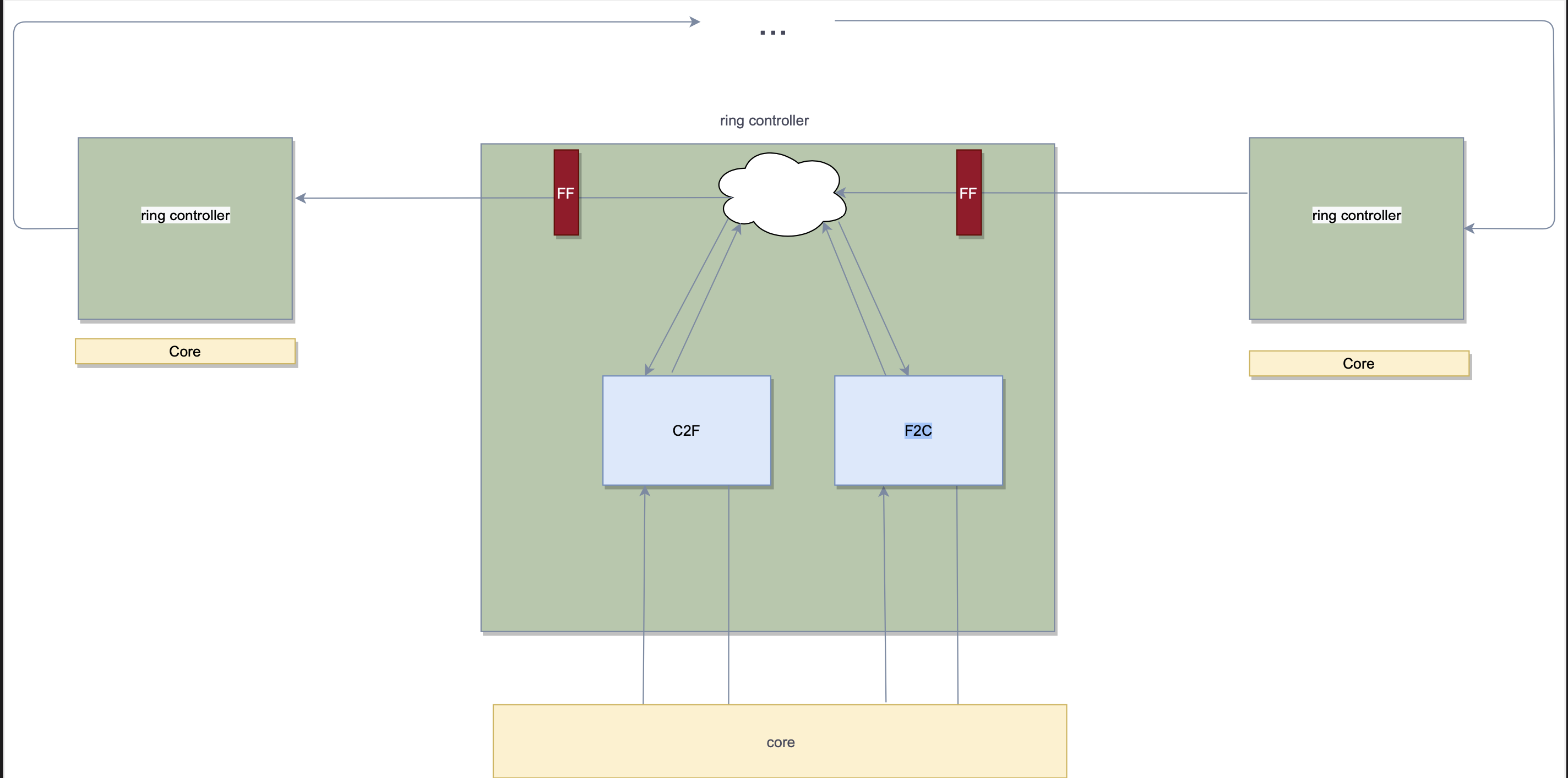
HAS RING_CTRL RC
The Ring Controller (RC) processes and schedules read and write requests between its core and its fabric ring interface.
The RC has two buffers named FabricToCore(F2C) with round trip number of entries
round trip = number of cycles that takes to a request to return from the core.
and CoreToFabric(C2F) with number of entries that equal to the maximum threads number in each core.
Transactions can be:
From the fabric :
- read request (F2C_RD).
- read response (F2C_RD_RSP).
- write request (F2C_WR).
- write broadcast request (F2C_WR_BCAST)
From the core :
- read request (C2F_RD).
- read response (C2F_RD_RSP).
- write request (C2F_WR).
- write broadcast request (C2F_WR_BCAST)
F2C stores transactions commands that received from the fabric ring interface to the core.
each transaction can be "pulled" to the F2C buffer if the address offset is in the core range && the opcode is RD/WR only .
Assuming each core has specified range of address.
todo - add explanation about broadcast
C2F stores core's read commands, which waits to get responded from the ring.
C2F can contain also read and write request , that will be in the buffer in case the ring interface output is busy .
The Rd_RSP can be "pulled" to the C2F buffer if the Opcode is RD_RSP && the req Address matches a pending buffer entry req address when a core thread sends a read request, it waits until that read response arrives.
each transactions has the following struct : Data,Address,Header,Valid.
Tzahi Shimi -> TBD , consider working with unified command structure , or divide between rd and wr
The interface between the core and the RC consists from 4 parts :
F2C->core : input from the F2C .
C2F->core : input from the C2F .
core->F2C : output to the F2C .
core->C2F : output to the C2F .
in every cycle, transactions can be sent simultaneously to and from the core. Once C2F is full ,it raise a stall signal , which notify the core that it would not be able to receive new transactions from the core.
C2F raise a stall signal when it is full && the core send a new request.
if the core sends to F2C read response , the relevant slot would change its state .
The core interface supports transaction that are consisted from valid ,opcode, address and data bits.
Assume thread number is 4 - in encoded form
| Signal Name | Direction | Description |
|---|---|---|
| C2F_ReqValidQ500H | Input | valid transaction indication |
| C2F_ReqOpcodeQ500H[1:0] | Input | Command type - RD=00 , RD_RSP=01 ,WR=10 , WR_BCAST=11 |
| C2F_ReqThreadIDQ500H[1:0] | Input | threadID |
| C2F_ReqAddressQ500H[ADDR_WIDTH-1:0] | Input | Request address |
| C2F_ReqDataQ500H[DATA_WIDTH-1:0] | Input | Write request data |
| C2F_RspValidQ502H | Output | valid transaction indication |
| C2F_RspOpcodeQ502H[1:0] | Output | Command type - RD=00 , RD_RSP=01 ,WR=10 , WR_BCAST=11 |
| C2F_RspThreadIDQ502H[1:0] | Output | threadID |
| C2F_RspDataQ502H[DATA_WIDTH-1:0] | Output | read response data |
| C2F_RspStall | Output | Disable the core from sending more commands |
C2F_RspAddress is not necessery , because the thread already knows the read address .
| Signal Name | Direction | Description |
|---|---|---|
| F2C_RspValidQ500H | Input | valid transaction indication |
| F2C_RspOpcodeQ500H[1:0] | Input | Command type - CRD=00 , RD_RSP=01 ,WR=10 , WR_BCAST=11 |
| F2C_RspAddressQ500H[ADDR_WIDTH-1:0] | Input | Request address |
| F2C_RspDataQ500H[DATA_WIDTH-1:0] | Input | Write request data |
| F2C_ReqValidQ502H | Output | valid transaction indication |
| F2C_ReqOpcodeQ502H[1:0] | Output | Command type - RD=00 , RD_RSP=01 ,WR=10 , WR_BCAST=11 |
| F2C_ReqAddressQ502H [ADDR_WIDTH-1:0] | Output | Request address |
| F2C_ReqDataQ502H [DATA_WIDTH-1:0] | Output | Write request data |
The request will be stored in one of the entries in the relevant buffer ,will be pending for execution . Core requests stored in C2F buffer .
Core requests = RD_REQ,WR, WR_BCAST Requests from the ring , that are relevant for the core, stored in F2C Ring requests = RD_RSP. each slot in the buffer , hold one state from the following : FREE, WRITE, READ, READ_PRGRS ,READ_RDY FREE indicates the slot is empty WRITE indicates the request type is write READ indicates the request type is read & still didn't sent to the core . READ_PRGRS indicates the request type is read & sent to the core & still not responsed. READ_RDY indicates the request type is read & the core supplied the data - ready to be sent to the ring .
For write request from core to ring : send request on the ring.
For write request from ring to core : send request to the core.
For read request from core to ring : send request on the ring, wait for read response from the ring and send the relevant data to the core.
For read request from ring to core : send request to the core wait for read response from the core and send the data on the ring.
Once the RC gets a read response - it check first if the address matches his address range .if so , it go over the C2F buffer entries , and check for the entry that has the same address .
The RC communicates with other RC with the Ring Interface.
The interface has two parts - The input bus and the output bus.
| Signal Name | Direction | Description |
|---|---|---|
| RingInputValidQ500H | Input | valid transaction indication |
| RingInputOpcodeQ500H[1:0] | Input | Command type - RD=00 , RD_RSP=01 ,WR=10 , WR_BCAST=11 |
| RingInputAddressQ500H[ADDR_WIDTH-1:0] | Input | Request address |
| RingInputDataQ500H[DATA_WIDTH-1:0] | Input | Write request data |
| RingOutputValidQ502H | Output | valid transaction indication |
| RingOutputOpcodeQ502H[1:0] | Output | Command type - RD=00 , RD_RSP=01 ,WR=10 , WR_BCAST=11 |
| RingOutputAddressQ502H[ADDR_WIDTH-1:0] | Output | Request address |
| RingOutputDataQ502H[DATA_WIDTH-1:0] | Output | Write request data |
Write requests are completed as soon as they are sent on the ring.
Read requests that waits for data are held in the relevant buffer slot, until appropriate data response arrived with the wanted data .
Then the data & accordance address & threadID sends to the core ,in order to get/send the new data and to wake up the waiting thread.
No need to rsp with the full 32 bit Address. Tzahi Shimi - we didnt understand the intention of that
- Request should be sent on the ring in the order they come in from the core.
- Pending read requests in the C2F buffer , would change their state to RDY when a matching read response received , and in the next cycle they can be sent to the ring .
No need for re order - because it keeps only read commands - read commands doesn't invoke dependcies issues.
- Pending request in F2C buffer , should be commit in the order they were sent.
- The core thread will not send any request , until it get responded to his first read request.
- When C2F buffer is full, raise a stall signal .
- When the RC gets a transaction that it is not the addresee , the incoming transaction will be forwarded immediately.
- When the RC gets a transaction that it cannot handle, because its relevant buffer is full, the incoming transaction will be forwarded immediately.
- In order to certify progress , and to avoid deadlocks , it is necessary that at least one of every four cycles , would be invalid .
would be certified by that each RC would count the cases when it receives invalid request from the ring input , and it send a valid request to the ring output . when this counter reach 4 , the RC must send a nop .( in that case ,also reset the counter) this counter would be reset in case the RC send to the ring output invalid request.
ABD - we will talk more about it. whatever we decide we need to write a well defined and explained paragraph about it.
The ring controller operates by unified external synchronized clock that all the controllers units gets in the same time. the controller also receives a synchronous(FIXME) reset signal used to clear any requests in both of the buffers when the system powered up.
| Signal Name | Direction | Description |
|---|---|---|
| QClk | Input | unified external synchronized clock signal |
| RstQnnnH | Input | synchronous reset signal |
The ring controller is required to expose the number of request slots in F2C and C2F to its top level module.
| parameter | Default value | comment |
|---|---|---|
| C2F_buffer_size | 4 X (size_of_request+size_of_response) | number of slots >= 4 and power of 2 |
| F2C_buffer_size | 4 X (size_of_request+size_of_response) | number of slots >= 4 and power of 2 |