-
-
Notifications
You must be signed in to change notification settings - Fork 32
ESP32 S2 DA

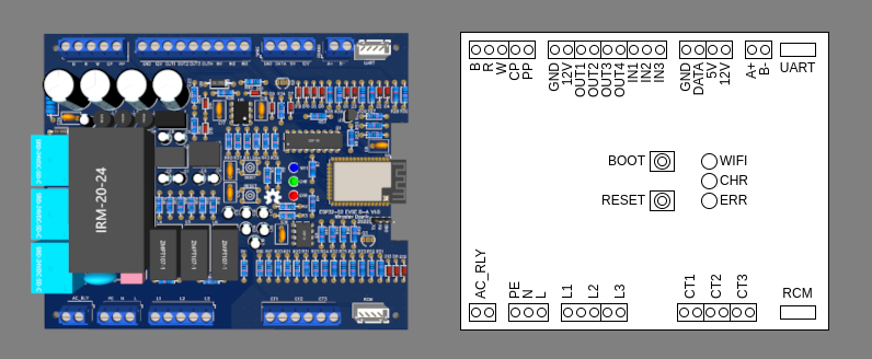
The dimensions of the board are 150x122 mm, designed to fit into the UM122 enclosure.
| Name | Meaning | Note |
|---|---|---|
| BOOT | Activate WiFi AP, during restart enter flashing mode | ESP gpio0 pin |
| RESET | Restart controller | ESP en pin |
| Name | Meaning | Color | Description |
|---|---|---|---|
| WIFI | WiFi | Blue | on - connected to WiFi flashing (on/off 100/900ms) - Started WiFi AP flashing (on/off 1900/100ms) - WiFi AP has client connection |
| CHR | Charging | Green | flashing - vehicle connected but not charging on - vehicle charging |
| ERR | Error | Red | on - is in error state (E) flashing - is in not available state (F) |
| Name | Meaning | Note |
|---|---|---|
| B | Detection of the locking actuator | |
| R | Control of the locking actuator | |
| W | Control of the locking actuator | |
| CP | Control Pilot | |
| PP | Proximity Plug | |
| GND | Ground | System ground |
| 12V | 12V | |
| OUT1 | Low side output 1 | |
| OUT2 | Low side output 2 | |
| OUT3 | Low side output 3 | |
| OUT4 | High side output 1 | |
| IN1 | Digital input 1 | |
| IN2 | Digital input 2 | |
| IN3 | Analog input | |
| GND | Ground | System ground |
| DATA | 1-Wire bus | For external temperature sensor DS18B20 |
| 5V | 5V power supply | |
| 12V | 12V power supply | |
| A+ | RS-485 A+ pin | RS-485 bus with 120Ω terminator resistor |
| B- | RS-485 B- pin | RS-485 bus with 120Ω terminator resistor |
| UART | UART serial bus (with 5V power supply) | |
| AR_RLY | Relay output for AC contactor | |
| PE | Protective Earth | Conetected to system ground |
| N | Neutral | Neutral conductor, power grid |
| L | Line | Phase, power grid |
| L1 | L1 voltage input | |
| L2 | L2 voltage input | |
| L3 | L3 voltage input | |
| CT1 | L1 current transformer | |
| CT2 | L2 current transformer | |
| CT3 | L3 current transformer | |
| RCM | Residual current monitor | RCM14-01 |
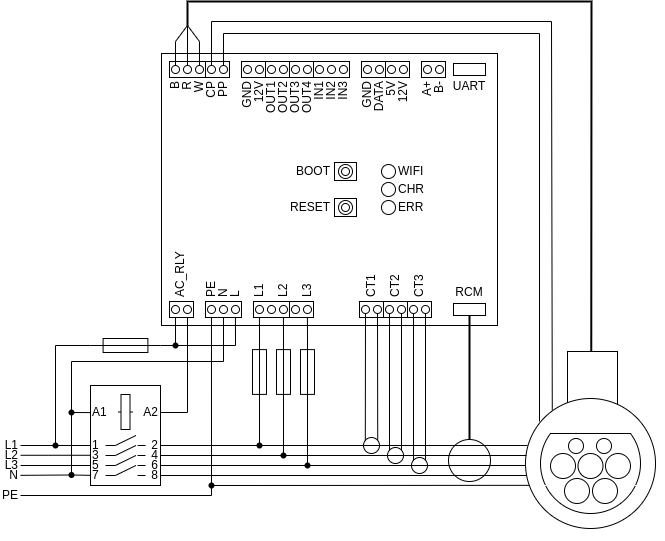
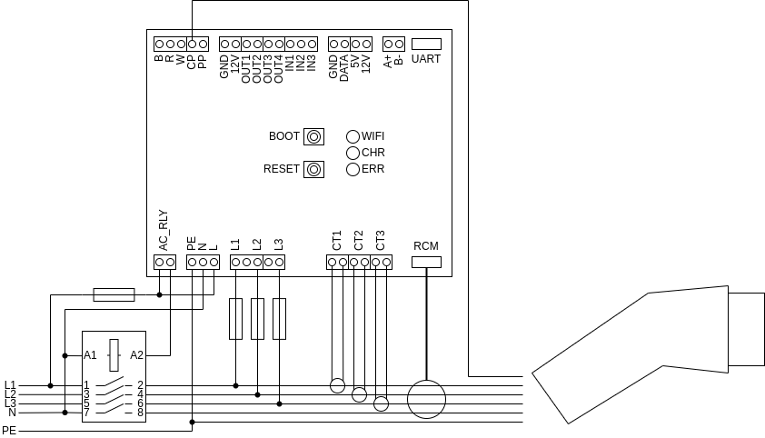
L1 - L3 connection is for measuring charging voltage, they are optional.
CT1 - CT3 are current transformers for measuring charging current, they are optional. Can be used any which has ratio 2000/1 (for example: DL-CT08CL5 or SCT-013-000).
When you have setup without current transformers and voltages connection set Energy meter Mode to Dummy, power will be calculated from actual charging current and provided AC voltage.
When you have only current transformers, can be set Energy meter Mode to Current sensing, power will be calculated from measured current and provided AC voltage.
When you have current transformers and voltages connection, can be set Energy meter Mode to Current and voltage sensing, power will be calculated from measured current and voltage.
Remember set Energy meter Three phases depending on whether you have a single-phase or three-phase connection.
Residual Current Monitor (RCM) is optional, if is not available it must be disabled in settings.

Set Max charging current to the value of the circuit breaker that protects the EVSE.

Set Max charging current to the lower value of the circuit breaker that protects the EVSE or cable maximum current.
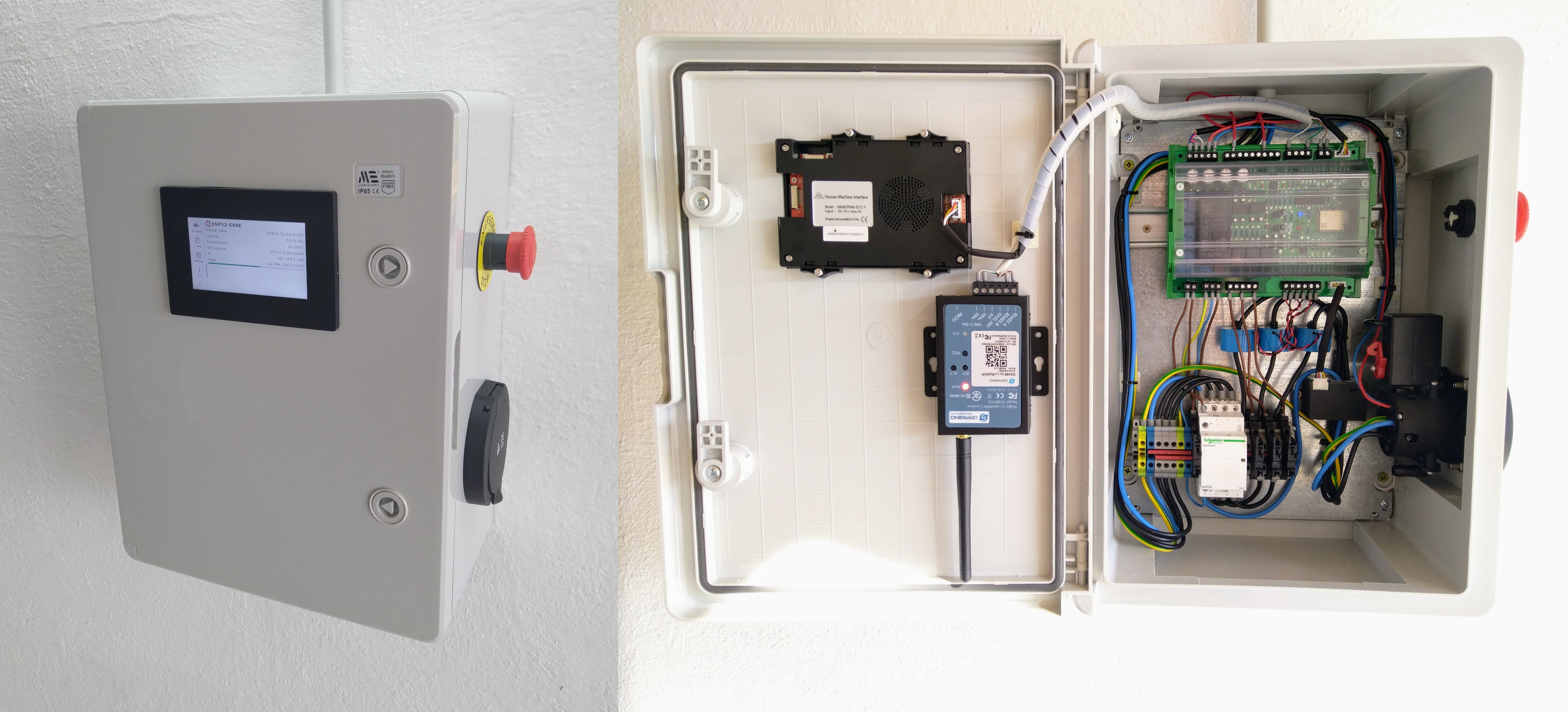
Placed in standard plastic electrical box (300x400x200mm). Based on connection with socket outlet with additional features:
- Low tariff enable input
- RCM
- Nextion display NX4827P043-011C-Y
- Dragino LoraWAN module

Emergency stop button not wired yet...