07. Commutators
If you have any questions please email hfawce@bu.edu

The ActiveComm is a simple low noise active (driven by a motor and sensor) commutator designed for ABA electrophysiology and optophysiology.

The .stl files for these parts can be found using the links below:

This PCB allows the same commutator to be used for electrophysiology. The CAM files for this PCB can be found for both the mezzapede and hirose connectors. We will be using the 14 pin hirose connectors.
This PCB can be assembled using a reflow oven to connect the Hirose and PZN-12 connectors as they are fairly small. After the connectors are soldered on, secure them with dental acrylic or Krazy Glue. The assembled board is shown below.

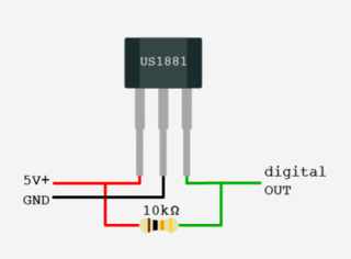
Compatible with both the A1324-LUA and A1301-LUAT Hall sensors. The commutator PCB takes care of the placement and connection of the 10k resistor.

Parallax Feedback 360 degree High-Speed Servo

Remove the drive plate from the drive shaft of the Servo and sandwich the Commutator linker between the flat gear and Servo. The drive shaft should fit snugly in the hole that extends above the base. Secure the gear to Servo using Krazy Glue or another strong adhesive, taking care to ensure that the motor can still turn.

Attach the second gear and thread the wires of the slip ring through the center hole. The slip ring should fit onto the printed pegs. Secure it in place using Krazy Glue. Place glue on the arm and fit the PCB onto the pegs printed on the arm. Position gears and secure the Servo to the linker so that the pegs fit through the mounting holes (we use hot glue). For wiring info, see below.

Secure the Arduino to the Servo and linker using glue or zip ties, then wire the PCB according to the diagrams below.

If you are using the lighting circuit board detailed in the DAQ assembly guide, follow the DB26 wiring scheme below:

The following diagrams are color-coded with the wire colors of the slip ring:


Notice that the 5V power and ground wires are attached to both the Ha3 and Ha2 vias as well as the PWR and GND vias. We achieved this by running a longer length of stripped wire through the GND and PWR vias and then adding additional jumpers to Ha3 and Ha2, respectively. Next, jumpers were soldered to Ha4, Ha5, and Ha6 which then connected to the appropriate pins on the Hall Effect sensor. Ha4 jumps to the signal pin, Ha5 jumps to the ground pin, and Ha6 jumps to the 5V pin. The use of jumpers allows the Hall Effect sensor to be placed in the desired location.
The wire from the top of the slip ring that is connected to via Ha1 (this wire is white in our case) is connected to port A0 on the Arduino Uno and does not go to the DB26 connector.
The wire from via H9 (black and white) also does not go to the DB26. When it comes out of the top of the slip ring, this wire is attached to a coaxial cable with a grounded shield. This coaxial cable is fitted with the coaxial cable connector so that it can be attached to the UCLA DAQ in the DAQ Box.
The PWR and GND wires (red and black) are split off so that they can be connected to both the DB26 and the Arduino on the commutator.
The power and ground wires from the servo are also attached to the 5V and GND ports on the commutator Arduino and the white signal wire is connected to port 9. The yellow servo wire is used for feedback which is not necessary for our purposes.
The full wiring of the commutator is shown below:
At this point, the DB26 can be connected to the Female DB26 connector on the DAQ Box and the coaxial cable from the commutator can be attached to the UCLA DAQ in the DAQ Box.
Get the code for the Arduino Uno here
To test your commutator, run the serial monitor in the Arduino IDE. This will read the values from the hall sensor. It should read 512, in the absence of a magnet. It will fluctuate +/- 30 depending on the displacement of a magnetic field. If the gears turn when the magnet is in the neutral position, adjust the setpoint position slightly.