-
Notifications
You must be signed in to change notification settings - Fork 8
Prepare PTC Creo Mechanism for URDF
Warning: the following procedure works only with MATLAB <= R2017b and Creo <= 8.
The CAD model of a robot is too complex to directly obtain a URDF from it and is divided into sub-assemblies following the assemblies' logic and sequence, so does not respect the division into "links". It's necessary to obtain a model that is:
- geometrically simplified
- differently assembled
- with the correct masses and inertial matrix values of the sub-parts
- with additional frames (datum, axes, frames) to assemble the sub-parts
The main workflow to obtain a URDF file starting from a CAD model is as follows:
CAD (Creo) → SimMechanics (MathWorks) → URDF
Hereafter is a quick overview of the process's main concepts, with reference links to the official documentation:
- datums and frames
- simplified representations
- shrinkwraps
- mechanism
- SimMechanics XML
- SimMechanics-to-urdf
The workflow described in this page is based on several assumptions regarding the source CAD model that is used to generate the simulation model. The main one is that the robot subassembly tree reflects the assembly structure. This, in turn, often results in sub-assemblies that comprise parts of different links.
A Creo assembly is not assembled with "mechanism" constraints because it would be too complex to manage and would require too many hardware resources. Moreover, the CAD model has to respect the robot's sub-assemblies' mounting sequence and logic, and this implies that the subdivision in sub-assemblies does not correspond to the subdivision in link geometries.
In the following sections, we define the guidelines to generate a Mechanism model compliant with the iCub Tech Facility standards.
The first part of the process consists of generating link geometries. This is done by grouping together parts that move together into single geometries.
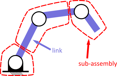
To do this, the Creo Parametric feature of simplified representations is employed. In particular, every link will be represented by a corresponding simplified representation.
In selecting components, pay attention to not forgetting any part belonging to the link. As detailed in the following procedure, a best practice is to include all the assemblies containing at least one link part, and subsequently exclude all the parts not belonging to the link.
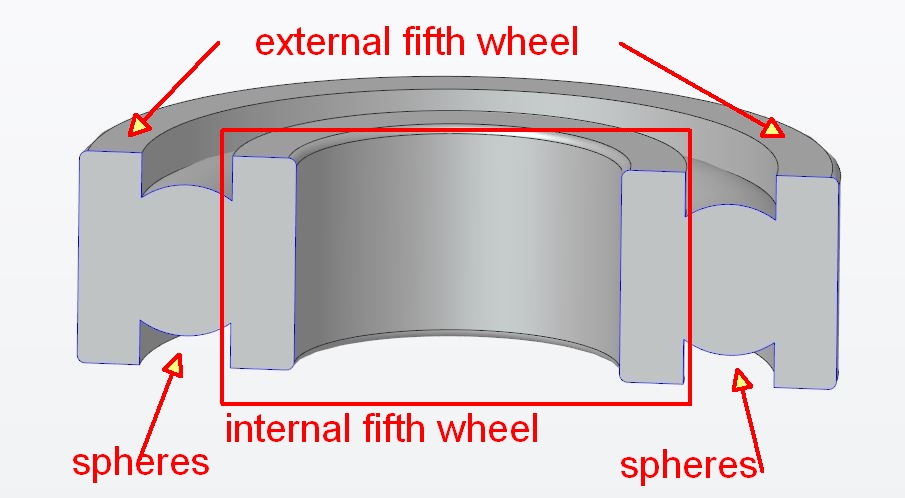
There are some components whose corresponding parts contain a joint within. For example, the bearings and the harmonic drives.
In this particular case, we decided as a standard that
- the whole bearing must be included in the link containing the outer ring.
- the harmonic drive has to be included in the link where its main part belongs. Nevertheless, if it is possible to differentiate between its components, it is better to make the wave generator linked to the motor shaft.
Finally, it is of fundamental importance that the mass of the Simplified Representation is equivalent to the mass of the real link.
The CAD model shall be updated to contain also a series of datum geometries (axis, planes, frames) that will be used to generate the URDF model. Specifically, we have to create geometries that will be used to assemble the Mechanism model and define the corresponding joints and geometries that will be used to define the location of specific sensors of the robot.
These datums have to be created in the smallest assembly that "represents" the joint:
- a joint axis
joint_name_AXIS - a joint translation plane
joint_name_TR_PLANE(perpendicular to the axis, it indicates at which point of the axis the two links have to be) - a joint reference plane
joint_name_RF_PLANE(through the axis, moving with the joint, it indicates how many degrees the joint rotates) - a link frame
SCSYS_link_namedefined as follow:- X-axis pointing forward
- Z-axis pointing up
- Y-axis to complete the right-handed triplet
- one of the axes has to be coincident with the parent joint axis
when it's not applicable:
- Z-axis is the one pointing upwards at the most
- X-axis pointing forward at the most
- Y-axis to complete the right-handed triplet
- one of the axes has to be coincident with the parent joint axis
N.B.
link frames could be created at the "local top-level" (i.e. upper body, right arm, legs....)
Since there are anatomical parts that can belong to different robots ( e.g. the head) we can consider them a stand-alone robot. For example, let's consider the head:
- Has its own
root_linkfrom which it starts its own model tree - Simp rep for head's sub-links are in the head assembly (not in the whole robot assembly)
- Both the parts contain a frame named
parentlink_childlink_interface_csys(e.g. CHEST_NECK_INTERFACE_CSYS) - They will be mounted in the mechanism with a frame-frame
User defined-Fully constrainedjoint
Concerning the frames used to define the sensor's position and orientation we can have:
- The measurement frame of the accelerometers.
- The measurement frame of the gyroscopes.
- The measurement frame of the IMUs.
- The measurement frame of the 6-axis Force Torque sensors.
- The measurement frame of the centre of the skin triangles.
These SF must be created at the sensor's lowest possible level to avoid duplicated names. This is fundamental because when we'll generate the SimMechanics model Creo needs to know which frame to export. The sensor's lowest possible level is defined as follows:
It is the lowest possible level that allows for avoiding to have duplicated values.
Eventually, it is really important to define a proper nomenclature for the SF, in order to easily retrieve them during the Shrinkwrap generation step (see below in the "How To Generate a Shrinkwrap" section).
Let's see from an operative point of view all the necessary steps to create the Creo Mechanism model and to generate the SimMechanics model.
Before proceeding, it is necessary to perform some preliminary operations:
- Check the robot mass, verify the correctness of density and material parameters of all the sub-components and possibly main sub-assemblies;
- Prepare a document that describes link and joint naming. As an example, these are the standards already defined for the iCub robot in iCub_Model_naming_conventions.
- Identify all the links that contain six-axis force-torque sensors. These links shall be split at the sensor measurement frame into two parts and shall be assembled in the Creo Mechanism model using a fixed joint. As an example, the following picture shows the location of the sensor measurement frame and the resulting link division.
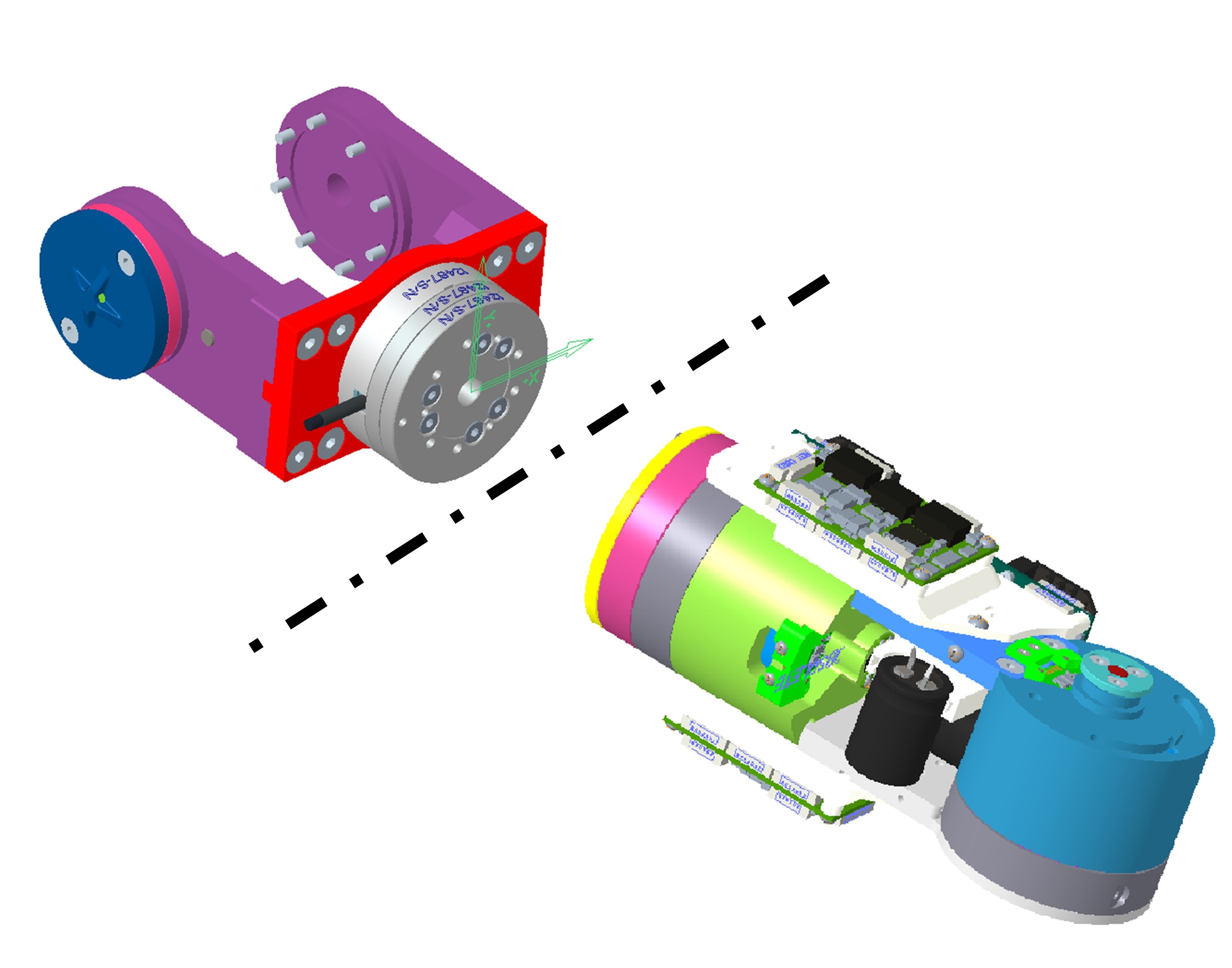
Note: due to a limitation of the SDF format used in the Gazebo open robotic simulation environment, the FT sensor frame origin must be centred with the origin of the child link frame of the joint to which the FT sensor is attached. This recommendation regards only the position of the FT sensor frame, but its orientation follows the rules described here.
- Prepare a document that describes the name and location of all the additional sensors.
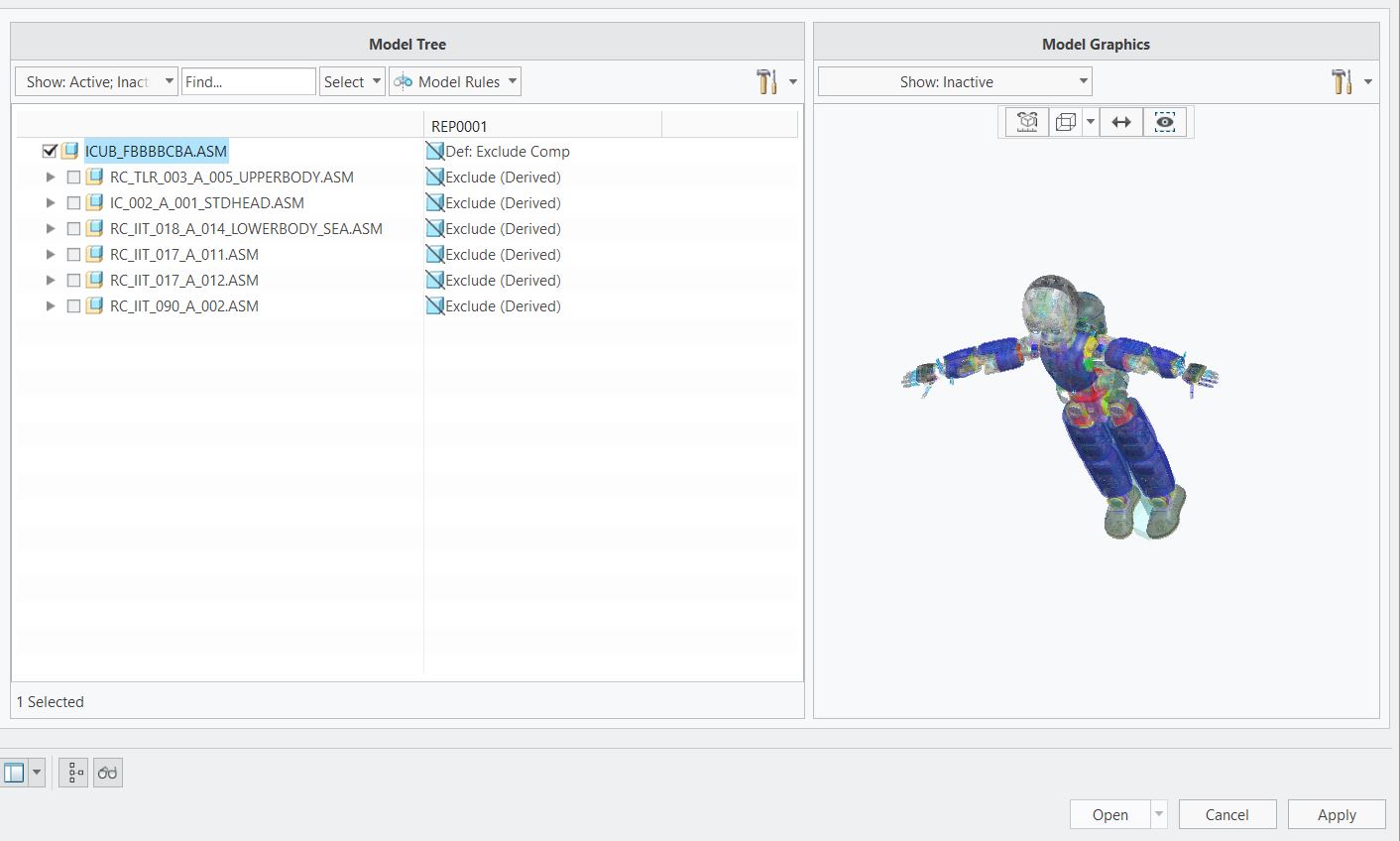
- Open the top-level assembly and create a new simplified representation (Simp Rep) to group parts. Name the simplified representation as:
SIM_robot name_ `name of the link that it represents.

- Set the main assembly in the "master rep" state, to ensure not to forget any of the parts.
- In the
Model Graphicswindow set as "visible" all components are in the "active" state. - Select all the components that belong to the link, and exclude all the parts that do not belong to the link. Pay attention to including all the parts, including screws!
- Open the main assembly.
- Open the proper simplified representation to add datums. Remember, they are related to joints.
- Add datums we created here related to the parent joint, child(ren) joint(s) and the link frame
- Open the main assembly.
- Open the proper simplified representation to add frames. Remember, they are related to links.
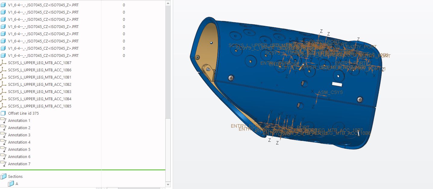
- Add frames with the proper nomenclature by adding a prefix related to the frame.
For the electronic boards and sensors frames, we decided on the following standard:
SCSYS _ link name _ sensor name.
Possiblesensor names:
-
FT- Force Torque sensor (either 45 or 58) -
IMU- Inertial Measurement Unit -
DEPTH- depth sensor -
RGB- classical RGB camera -
ACC- accelerometer -
SKIN- skin, see the dedicated section
WIP The following details the procedure to generate a model representing the skin topology.
The skin is a distributed pressure sensor composed of a flexible PCB covered by soft tissue. On the robot, the skin is organized in patches, which represent a collection of PCB triangles physically and electrically connected. Each triangle is equipped with a controller, positioned in the triangle centre, and 12 tactile sensors, called taxels. The goal of this procedure is to obtain the position of the taxels with respect to the coordinate frame of the skin-covered link. The process consists of two phases. During the first phase, the position of the triangle centres is extracted from the CAD model and written in a URDF file. In the second phase, the knowledge of the centres' position is exploited to compute the position of each taxel.
Include triangle centres in the URDF
The easiest way to represent the position of the triangle centres is by using a coordinate frame. Considering that the URDF robot description format doesn't allow to define multiple frames within a single link, the centre of each PCB triangle is represented in the URDF model as a dummy link fixed to the skin-covered link.
For this purpose in the CAD model of the robot, it is necessary to add one coordinate frame for each skin triangle centre.
The following convention shall be used when defining the coordinate frames:
- Each coordinate frame shall be labelled accordingly to the following standard:
- SCSYS _ L/R (if side dependent) _ BODY PART (e.g. torso, upper arm, forearm) _ SKIN _ "triangle number" (ask to electronic department);
- Each coordinate frame shall be oriented with the
Zaxis normal to the skin surface (pointing outward) andXoriented along the main dimension of the skin-covered link (direction is arbitrary, but shall be consistent); - The best level in the assembly tree to add the coordinate frame is the lowest (i.e. most nested) assembly.
Compute the taxels position
By fitting the 2D patch geometry (with taxel position information with respect to triangle centre) with the position of the triangle centres expressed in 3D it is possible to compute the position of each taxel with respect to the limb.
This computation is performed by the script https://github.com/robotology-playground/icub-model-generator/blob/master/simmechanics/scripts/generate_taxels_3d_positions.py .
TBD
Here below the steps that are necessary to complete the task:
- Open the main assembly.
- Open the proper simplified representation that must be shrinkwrapped.
- Save As - Type ShrinkWrap
- Select the creation method (Faceted Solid).
- Select the quality (6-9) (if the meshes are not well generated, try to decrease the quality)
- Select the references (e.g. axis, planes, ...) (see the rules in the joints that have been decided and defined in the aforementioned passages with the "Include Datum References" > "Select Datum" option to assemble the robot mechanism afterwards.
- Give it the same name as the SimpRep

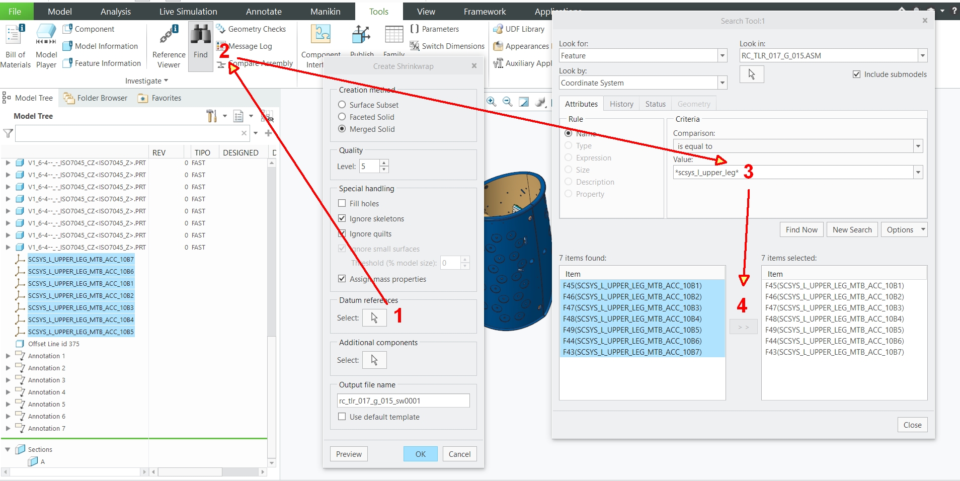
- To include the correct datum references is really useful the "find" tool, after having properly named frames and references as previously described. Hereafter we can see an example
We want to include in the shrinkwrap the frames of the MTB boards.
- select "Datum references" [1]
- Click the "find" tool [2]
- define a query and what kind of references you are searching for if necessary use asterisks [3]
- select the references and include them in your shrinkwrap. [4]
- Check the "Assign mass properties" checkbox
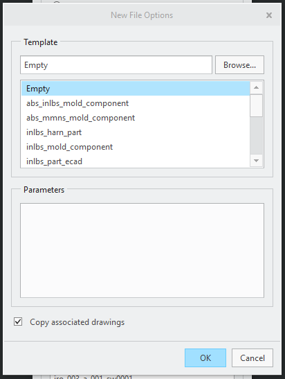
- Uncheck the "Use default template" checkbox and select the correct template
-
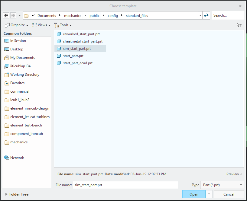
Browse the sim_start_part.prt file
-
Select the accuracy (suggested value is fine).
-
Save it in
cad-mechanics\projects\simulation_model -
For each link in the link list, we have to repeat the aforementioned procedure.
-
Avoid using mirror geometry but double-check that symmetric assemblies (left forearm and right forearm for example) have the same masses and inertial values!
Create a new simulation mechanism and assemble the robot using the shrunk parts. Pay attention to assembling it as the original one.
- root link has to be the first part of the assembly.
- link should be assembled using the datums we created (axis, transition plane, reference plane).
- joints have to be set in zero position.
- FT sensors have to be considered as joints, the FT sensor as a whole belongs to one of the links and is connected to the other with a frame-frame
User defined-Fully constrainedjoint. - assembly name is like
sim_icub3_upperbody.asm-sim_icub3.asm-sim_head. - it has to be stored in
cad-mechanics\projects\simulation_model
Refer to this page to correctly check the mass properties of each part and of the final assembly. Consider using the correct parameter also when computing the mass properties during the shrinkwrap generation.
After having obtained the CAD assembly file, we need to follow these steps:
- Generate the XML SimMechanics model
- Decrease the size of the meshes (if necessary, namely less than ~ 1 Mb in size)
- Create the URDF
- Input: CAD assembly files (the Creo Mechanism model created in the previous section)
- Output: XML model description file and .stl mesh files
- Matlab [version <= 2017a] The version is important because from version 2017b the first-generation CAD exportation has been deprecated
- Simscape Multibody Link Plug-In [version <= 5.0] Follow this guide for the installation
-
Open the CREO Mechanism
-
Go to Tools\Simscape Multibody link\Settings

- Select the settings
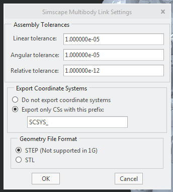
- Export the model selecting Tools\Simscape Multibody link\Export\Simscape Multibody First Generation (1G)

If the weight of the meshes is relevant, it's possible to reduce their size using MeshLab. Here
Here a YouTube Tutorial.
- Import the single mesh
- Select Remeshing, Simplification and Reconstruction\Simplification: Quadratic Edge Collapse Decimation

- Press apply and the number of faces will be reduced to one half
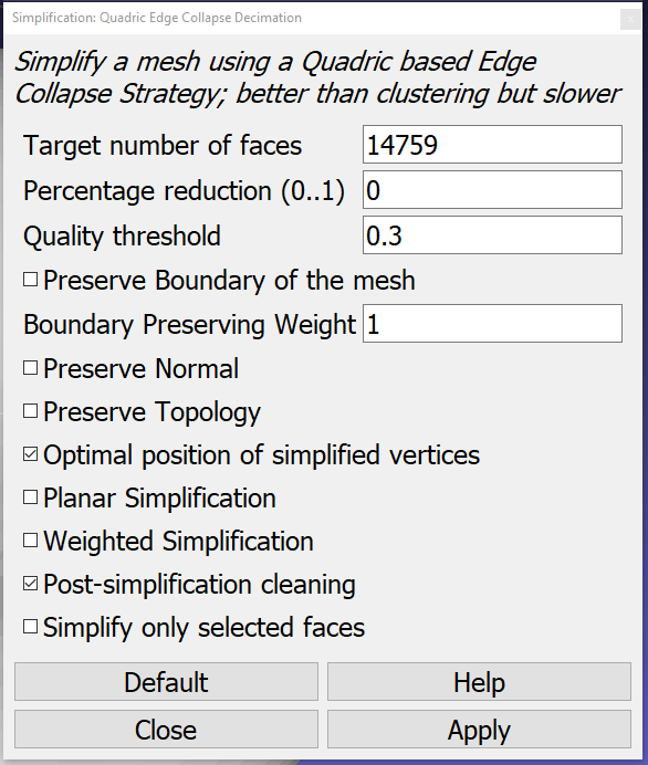
- When the desired reduction is achieved, save the new mesh
To convert from the SimMechanics XML model to the URDF model we exploit the tool simmechanics-to-urdf, authored by Silvio Traversaro.
Input: SimMechanics XML model. Optional inputs: .csv file with joint and actuator specifications, yaml configuration file. Output: URDF XML file.
