Download "RASPBIAN JESSIE LITE" https://www.raspberrypi.org/downloads/raspbian/
Create your new hard disk for DashboardPI
Insert the microSD to your computer via USB adapter and create the disk image using the
ddcommandLocate your inserted microSD card via the
df -hcommand, unmount it and create the disk image with the disk copyddcommand$
df -h/dev/sdb1 7.4G 32K 7.4G 1% /media/XXX/1234-5678$
umount /dev/sdb1Caution: be sure the command is completely accurate, you can damage other disks with this command
if=location of RASPBIAN JESSIE LITE image file of=location of your microSD card
$
sudo dd bs=4M if=/path/to/raspbian-jessie-lite.img of=/dev/sdb(note: in this case, it's /dev/sdb, /dev/sdb1 was an existing factory partition on the microSD)
Setting up your RaspberriPi
Insert your new microSD card to the raspberrypi and power it on with a monitor connected to the HDMI port
Login
user: pi pass: raspberry
Change your account password for security
sudo passwd pi
Enable RaspberriPi Advanced Options
sudo raspi-config
Choose:
1 Expand File System
9 Advanced Options
A2 Hostnamechange it to "MagicMirror"
A4 SSHEnable SSH Server
A7 I2CEnable i2c interface
Enable the English/US Keyboard
sudo nano /etc/default/keyboard
Change the following line:
XKBLAYOUT="us"
Reboot PI for Keyboard layout changes / file system resizing to take effect
$
sudo shutdown -r now
Auto-Connect to your WiFi
sudo nano /etc/wpa_supplicant/wpa_supplicant.conf
Add the following lines to have your raspberrypi automatically connect to your home WiFi (if your wireless network is named "linksys" for example, in the following example)
network={
   ssid="linksys"
   psk="WIRELESS PASSWORD HERE"
}
Reboot PI to connect to WiFi network
$
sudo shutdown -r nowNow that your PI is finally on the local network, you can login remotely to it via SSH. But first you need to get the IP address it currently has.
$
ifconfigLook for "inet addr: 192.168.XXX.XXX" in the following command's output for your PI's IP Address
Go to another machine and login to your raspberrypi via ssh
$
ssh pi@192.168.XXX.XXX
Start Installing required packages
$
sudo apt-get update$
sudo apt-get upgrade$
sudo apt-get install vim git python-smbus i2c-tools python-imaging python-smbus build-essential python-dev rpi.gpio python3 python3-pip libi2c-dev python-requests
Update local timezone settings
$
sudo dpkg-reconfigure tzdata
select your timezone using the interface
Setup the simple directory l command [optional]
$
vi ~/.bashrcadd the following line:
$
alias l='ls -lh'$
source ~/.bashrc
Fix VIM default syntax highlighting [optional]
$
sudo vi /etc/vim/vimrcuncomment the following line:
syntax on
DHT11 Install
$
cd ~$
git clone https://github.com/adafruit/Adafruit_Python_DHT.git$
cd Adafruit_Python_DHT/$
sudo python setup.py install$
sudo python ez_setup.py$
cd examples/$
vi simpletest.py
Change the following line:
sensor = Adafruit_DHT.DHT11
Comment the line out
pin = 'P8_11'
Uncomment the line and change the pin number to 16
pin = 16
Run the test
python simpletest.py
You should see a metric reading of Temp and Humidity displayed on the command line.
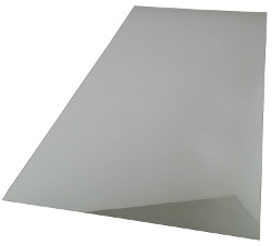
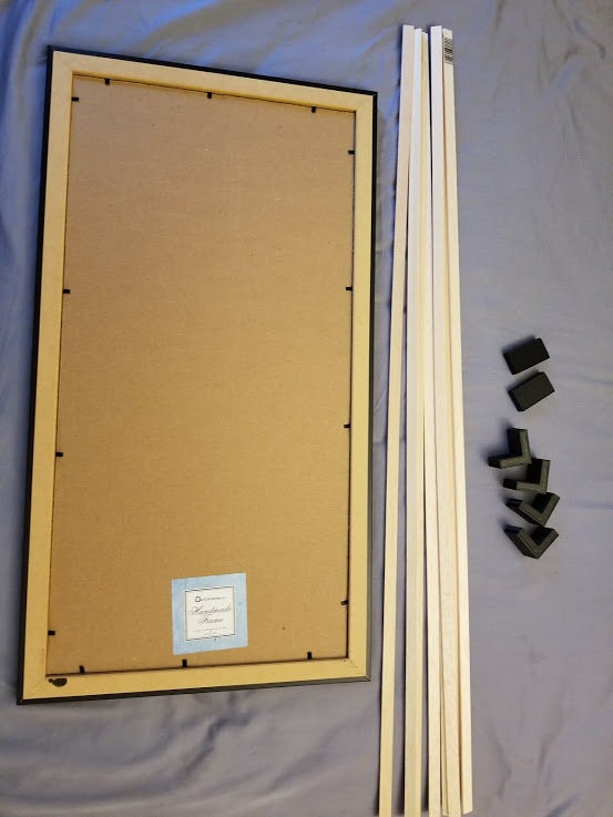
12" x 24" Acrylic See-Through Mirror, 3mm
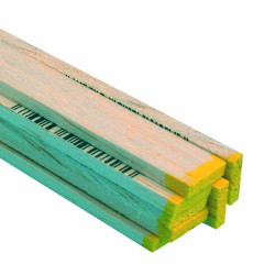
Balsa wood strips 0.125 x 0.5 Inches
12x24 inch Black Picture Frame
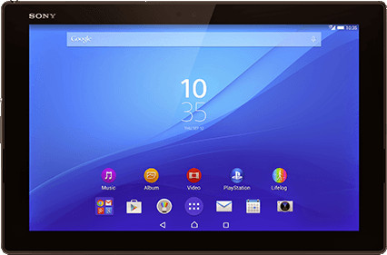
Android Tablets (x2)
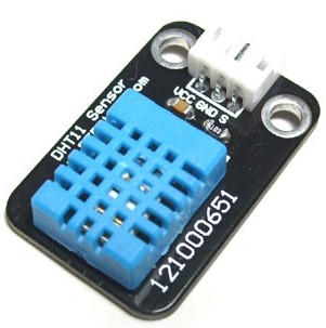
DHT11 Humidistat
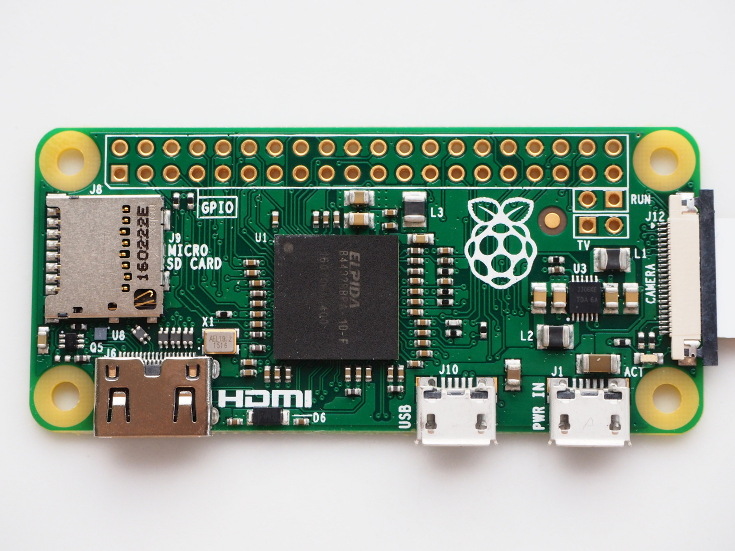
RaspberriPi Zero (or Regular RaspberriPi should work)
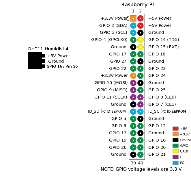
DHT11 Humidistat
VCC -> 5V
GND -> GND
DATA -> GPIO 16 / PIN 36
In the /construction folder of the project 3D print the following attachments to build the picture frame borders and tablet holders.
Print the Following Tablet Holders:
tablet-mounts.stl
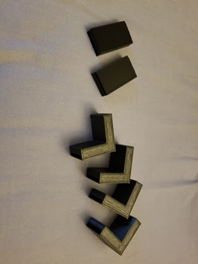
Print the Following Frame Corner blocks and balsa wood attachments:
mirror-corner-blocks.stl
mirror-corners.stl
mirror-sides.stl
Gather together the frame balsa wood strips and the 3D printed attachments
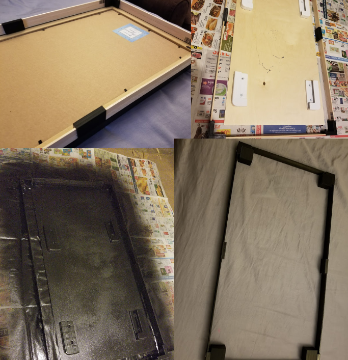
Assemble the balsawood strips inside the corner brackets (sliding the balsawood through the side brackets, make sure they're square against the corners of the picture frame. Paint everything black with spray paint.
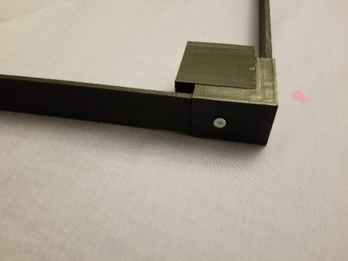
Screw the corners to the 4 corner blocks to hold the frame together.
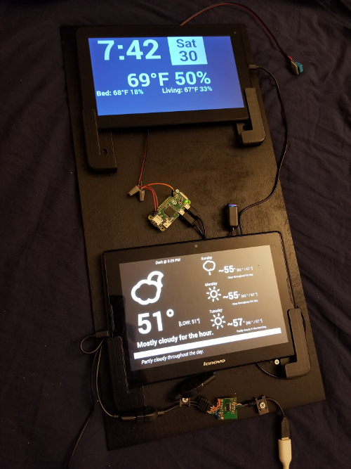
Attach the tablets and Raspberry PiZero to the wood to eventually fix to the wall.
Attach to the wall the board. (Note the 2 screws on the top left and right, they will be used to hold up the picture frame with frame border attached to place in front of the tablets to shine through the mirror)
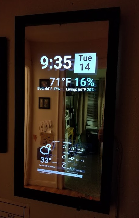
Finally replace the cardboard piece inside the picture frame with a two way mirror and on each corner of the picture frame screw into the corner (3D printed) blocks to hold the picture frame to the frame border.
Create the Device Hub Project hosted on a PHP enabled webhost of your choice for the top tablet to get data
https://github.com/khinds10/DeviceHub
https://github.com/khinds10/WeatherTablet
In the raspberrypi folder of the project copy the settings.shadown.py file to settings.py with the host file of the DeviceHub project above you have setup.
$
crontab -e
Add the following lines:
*/3 * * * * python /home/pi//MagicMirror/raspberrypi/temp-check.py
Verify the display starts working on reboot
$
sudo reboot
Create a PHP enabled website online with the contents of the "tablet" folder in this project.
Configure the website: In the "tablet/server" folder of the project, copy the config.shadow.php file to a file named "config.php" Edit the "config.php" configure the $deviceHubAPI value to point to the device hub of your choosing from the referenced project above (https://github.com/khinds10/DeviceHub)
Example Apache2 Configuration File for the tablet clock PHP website
<VirtualHost *:80>
DocumentRoot /var/www/tablet
ServerName myclocktablet.com
ServerAdmin webmaster@myclocktablet.com
ErrorLog
FINISHED!
