-
Notifications
You must be signed in to change notification settings - Fork 0
1.3 Basic Arduino Projects
When programming with Arduino, we use two main functions: setup() and loop(). The setup() function runs once when you power the board or press the reset button, while the loop() function runs continuously.
When creating a new sketch, here is how your code will initially look:
void setup() {
  // put your setup code here, to run once:

}

void loop() {
  // put your main code here, to run repeatedly:

}To get started, let's print some messages to the Serial Monitor. These messages are called strings, which are sequences of characters that we can display. The Arduino executes the code inside these functions, and we can see the output on our computers. When we run this on the robot, the robot will also 'see' this output.
void setup() {
  Serial.begin(9600);           // Start serial communication at 9600 bits per second
  Serial.println("Setup is starting..."); // Print message to Serial Monitor
}
In this snippet, we begin serial communication and print a message indicating that the setup has started.
void loop() {
  Serial.println("Loop is running..."); // Print message to Serial Monitor
  delay(1000);                          // Wait for a second
}
Now, in the loop() function, we print another message and introduce a delay(1000), which pauses the program for 1000 milliseconds (or 1 second).
Compile the code and Upload it at this stage, to observe what your microcontroller can do at this point.
Toggling the Onboard LED Next, we will toggle the onboard LED of the Arduino, which is usually connected to pin 13.
To control the onboard LED, we need to set the pin mode in the setup() function. Let's modify the setup:
void setup() {
  Serial.begin(9600);                  // Start serial communication
  pinMode(13, OUTPUT);                 // Set pin 13 as an OUTPUT
  Serial.println("Pin 13 set as OUTPUT.");
}Now, let's turn the LED on in the loop() function.
void loop() {
  digitalWrite(13, HIGH);              // Turn the LED on
  Serial.println("LED is ON.");        // Print status to Serial Monitor
  delay(1000);                         // Wait for a second
}Next, we will turn the LED off.
void loop() {
  digitalWrite(13, HIGH);              // Turn the LED on
  Serial.println("LED is ON.");
  delay(1000);                         // Wait for a second

  digitalWrite(13, LOW);               // Turn the LED off
  Serial.println("LED is OFF.");       // Print status to Serial Monitor
  delay(1000);                         // Wait for a second
}
Now, when you upload this code, you will see the onboard LED toggling on and off every second, and the messages will appear on the Serial Monitor.
Now let’s connect an external LED on a breadboard. You will need:
- An LED
- A 220-ohm resistor
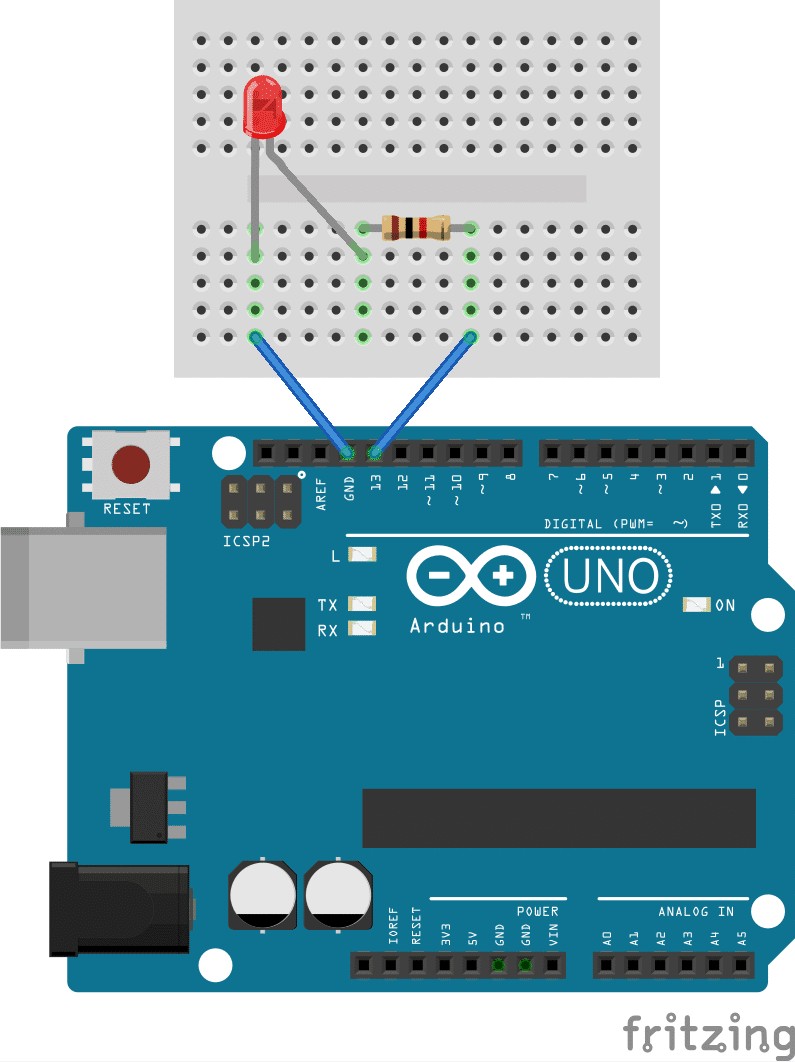
Perform the setup as in the following image

Connect the long leg (anode) of the LED to digital pin 13 on the Arduino. Connect the short leg (cathode) to one end of the resistor. Connect the other end of the resistor to the ground (GND) pin on the Arduino.
You can use the same code as before to toggle the external LED.
void setup() {
  Serial.begin(9600);
  pinMode(13, OUTPUT);
  Serial.println("Pin 13 set as OUTPUT.");
}

void loop() {
  digitalWrite(13, HIGH);
  Serial.println("LED is ON.");
  delay(1000);

  digitalWrite(13, LOW);
  Serial.println("LED is OFF.");
  delay(1000);
}Servos are motor devices that can rotate to a specific angle based on the input signal. They are commonly used in robotics for tasks that require precise control.
Before we dive into controlling the servo, let's start by printing messages to the Serial Monitor, just like we did with the LED. This will help us understand when the code is running.
Code Snippet:
void setup() {
  Serial.begin(9600);               // Start serial communication
  Serial.println("Setup is starting..."); // Print message to Serial Monitor
}

void loop() {
  Serial.println("Loop is running..."); // Print message to Serial Monitor
  delay(1000);                        // Wait for a second
}
Compile the code and Upload it. You should see messages indicating that the setup is running and the loop is executing.
To control the servo, we need to include the Servo library. This library simplifies the process of sending commands to the servo.
Code Snippet:
#include <Servo.h>                    // Include the Servo library

void setup() {
  Serial.begin(9600);
  Serial.println("Setup is starting...");
}

void loop() {
  Serial.println("Loop is running...");
  delay(1000);
}Next, we will create a Servo object that we will use to control the servo motor.
Code Snippet:
#include <Servo.h>                    // Include the Servo library

Servo myServo;                        // Create a Servo object

void setup() {
  Serial.begin(9600);
  Serial.println("Setup is starting...");
  myServo.attach(9);                 // Attach the servo on pin 9
  Serial.println("Servo attached to pin 9.");
}

void loop() {
  Serial.println("Loop is running...");
  delay(1000);
}Now, let's rotate the servo to different angles. We will move it to 0 degrees first.
Code Snippet:
#include <Servo.h>

Servo myServo;

void setup() {
  Serial.begin(9600);
  Serial.println("Setup is starting...");
  myServo.attach(9);
  Serial.println("Servo attached to pin 9.");
}

void loop() {
  myServo.write(0);                  // Rotate servo to 0 degrees
  Serial.println("Servo at 0 degrees.");
  delay(1000);                       // Wait for a second
}Next, we will move the servo to 90 degrees after a short delay.
Code Snippet:
#include <Servo.h>

Servo myServo;

void setup() {
  Serial.begin(9600);
  Serial.println("Setup is starting...");
  myServo.attach(9);
  Serial.println("Servo attached to pin 9.");
}

void loop() {
  myServo.write(0);
  Serial.println("Servo at 0 degrees.");
  delay(1000);                       // Wait for a second

  myServo.write(90);                 // Rotate servo to 90 degrees
  Serial.println("Servo at 90 degrees.");
  delay(1000);                       // Wait for a second
}Finally, we will move the servo to 180 degrees.
Code Snippet:
#include <Servo.h>

Servo myServo;

void setup() {
  Serial.begin(9600);
  Serial.println("Setup is starting...");
  myServo.attach(9);
  Serial.println("Servo attached to pin 9.");
}

void loop() {
  myServo.write(0);
  Serial.println("Servo at 0 degrees.");
  delay(1000);

  myServo.write(90);
  Serial.println("Servo at 90 degrees.");
  delay(1000);

  myServo.write(180);                // Rotate servo to 180 degrees
  Serial.println("Servo at 180 degrees.");
  delay(1000);
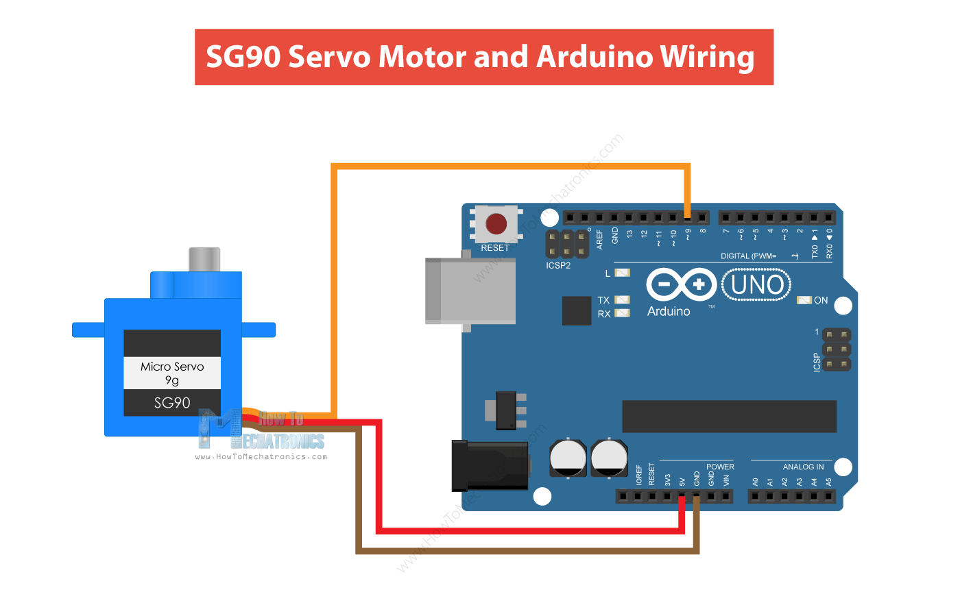
}To connect the servo, you will need:
- A servo motor
Wiring Instructions:
Connect the signal wire (usually white or yellow) to digital pin 9 on the Arduino. Connect the power wire (usually red) to the 5V pin on the Arduino. Connect the ground wire (usually black or brown) to the GND pin on the Arduino.

Now that you have everything connected, upload the complete code to your Arduino. You should see the servo moving to 0, 90, and 180 degrees, with corresponding messages appearing in the Serial Monitor.
Pushbuttons are simple devices that allow you to control the flow of electricity when pressed. In this project, we will use a pushbutton to turn an LED on and off.
We will start by setting up our project and printing messages to the Serial Monitor, so we know when the code is running.
Code Snippet:
const int buttonPin = 2;  // the number of the pushbutton pin
const int ledPin = 13;    // the number of the LED pin

void setup() {
  Serial.begin(9600);                 // Start serial communication
  Serial.println("Setup is starting..."); // Print message to Serial Monitor
}

void loop() {
  Serial.println("Loop is running..."); // Print message to Serial Monitor
  delay(1000);                        // Wait for a second
}
Compile the code and Upload it. You should see messages indicating that the setup is running and the loop is executing.
Next, we will initialize the LED and button pins in the setup() function.
Code Snippet:
const int buttonPin = 2;  // the number of the pushbutton pin
const int ledPin = 13;    // the number of the LED pin

void setup() {
  Serial.begin(9600);
  Serial.println("Setup is starting...");
  pinMode(ledPin, OUTPUT);         // Initialize the LED pin as an output
  pinMode(buttonPin, INPUT);       // Initialize the pushbutton pin as an input
  Serial.println("LED pin set as OUTPUT and Button pin set as INPUT.");
}

void loop() {
  Serial.println("Loop is running...");
  delay(1000);
}Now we will read the state of the pushbutton in the loop() function. This will allow us to detect when the button is pressed.
Code Snippet:
const int buttonPin = 2;  // the number of the pushbutton pin
const int ledPin = 13;    // the number of the LED pin

void setup() {
  Serial.begin(9600);
  Serial.println("Setup is starting...");
  pinMode(ledPin, OUTPUT);
  pinMode(buttonPin, INPUT);
}

void loop() {
  int buttonState = digitalRead(buttonPin); // Read the state of the pushbutton
  Serial.println("Loop is running...");
  delay(1000);
}Now, we will check if the button is pressed and control the LED accordingly. If the button is pressed (i.e., the button state is HIGH), we will turn the LED on; otherwise, we will turn it off.
Code Snippet:
const int buttonPin = 2;  // the number of the pushbutton pin
const int ledPin = 13;    // the number of the LED pin

void setup() {
  Serial.begin(9600);
  Serial.println("Setup is starting...");
  pinMode(ledPin, OUTPUT);
  pinMode(buttonPin, INPUT);
}

void loop() {
  int buttonState = digitalRead(buttonPin); // Read the state of the pushbutton

  // Check if the pushbutton is pressed:
  if (buttonState == HIGH) {
    digitalWrite(ledPin, HIGH); // Turn the LED on
    Serial.println("LED is ON.");
  } else {
    digitalWrite(ledPin, LOW); // Turn the LED off
    Serial.println("LED is OFF.");
  }
  delay(100); // Small delay to avoid rapid toggling
}To complete this project, you will need:
- A push button
- A 10k-ohm resistor
Wiring instructions: Connect one side of the pushbutton to 5V and the other side to digital pin 2. Connect a 10K-ohm resistor from pin 2 to ground (GND).

Now that you have everything connected, upload the complete code to your Arduino. When you press the pushbutton, the LED should turn on, and when you release it, the LED should turn off. You will see the corresponding messages in the Serial Monitor.