Skip to content
New issue

Have a question about this project? Sign up for a free GitHub account to open an issue and contact its maintainers and the community.

By clicking “Sign up for GitHub”, you agree to our terms of service and privacy statement. We’ll occasionally send you account related emails.

Already on GitHub? Sign in to your account

Surface from Net of Curves Node (Gordon Surface) #4183

Merged
merged 39 commits into from
Jul 4, 2021
Merged

Conversation

portnov
Copy link
Collaborator

@portnov portnov commented Jun 24, 2021

refs #3603

Given a net of intersecting curves, this node generates a surface which passes
through all given curves.

A net of curves is two sets of curves, one set along one direction and one set
along another. One set of curves is called "U-curves" (curves along U
direction) and another set of curves is called "V-curves" (curves along V
direction).

Apart of curves grid, this node requires intersection points of curves provided
explictly. Intersection points can be calculated by use of "Intersect NURBS
curves" node. Note: that node uses numeric algorithms to calculate
intersections, so it can fail to find intersections, or give imprecise results.
So, if you have intersection points in advance, it's better to use them.

This node generates a NURBS surface from NURBS curves according to algorithm
known as "Gordon Surface".

Screenshot_20210626_000816

Screenshot_20210704_115911

Screenshot_20210627_213402

Screenshot_20210627_192737

Screenshot_20210627_193025

Gordon surface algorithm has a number of restrictions:

  • All input curves must be NURBS or NURBS-like. More specifically, only non-rational curves are supported - i.e., without weights (or all weights equal).
  • All U-curves must have "the same" direction; all V-curves must also have "the same" direction.
  • There must be N curves along one direction, and M curves along another direction, which must exactly intersect at N x M points.
  • intersection points must be located evenly in parameter spaces of curves. For example, V-Curve C_v must intersect all U-curves C_u at the same value of U parameter.
  • U-curves must be ordered along direction of V-curves, and vice versa. For example, if U-curve C_u1 intersects V-curve C_v at v = v1, and another U-curve C_u2 intersects the same V-curve C_v at v = v2, and v1 < v2, then in input curves list, C_u1 must be provided before C_u2.

One relatively easy way to build a correct curves net is to draw a number of Bezier curves, which intersect exactly at their node points.

Planned developments:

  • Add "implementation" parameter to "Interpolate NURBS Surface" node. Currently this node depends on Geomdl. Now two implementation will be available: Sverchok (built-in) and Geomdl.
  • New "Intersect NURBS Curves" node. It will have two implementation: SciPy (algorithm in Sverchok, which uses SciPy minimization routines) and FreeCAD, and some settings about precision / tolerance.
  • New "NURBS Surface from Curves Net" node. It will have mandatory "Intersections" parameter, because finding curve intersections is a separate task, for which there will be specialized node with it's own parameters.

Preflight checklist

Put an x letter in each brackets when you're done this item:

  • Code changes complete.
  • Code documentation complete.
  • Documentation for users complete (or not required, if user never sees these changes).
  • Manual testing done.
  • Unit-tests implemented.
  • Ready for merge.

@portnov portnov marked this pull request as draft June 24, 2021 19:38
@portnov portnov added the NURBS label Jun 25, 2021
@portnov
Copy link
Collaborator Author

portnov commented Jun 27, 2021

@rendetto initial implementation of "NURBS Surface from Curves Net" node is more or less ready. It still lacks documentation, and there may be some tunings... but you may already try it from this branch.

@portnov
Copy link
Collaborator Author

portnov commented Jun 27, 2021

intersection points must be located evenly in parameter spaces of curves. For example, V-Curve C_v must intersect all U-curves C_u at the same value of U parameter.

The following is the most trivial approach to removing this restriction. Given a curve and a set of T-values at which it has intersections with other curves from the net, reparametrize the curve so that intersection points will be located evenly in curve's parameter space.

"""
in curve_in C
out curve_out C
"""

from sverchok.data_structure import zip_long_repeat, ensure_nesting_level
from sverchok.utils.curve import SvCurve
from sverchok.utils.curve.nurbs import SvNurbsCurve

def process(curve):
    t_values = [0.2, 0.3, 0.7, 0.8]
    t_min, t_max = curve.get_u_bounds()
    t_values = [t_min] + t_values + [t_max]
    
    segments = []
    for t1, t2 in zip(t_values, t_values[1:]):
        segment = curve.cut_segment(t1, t2, rescale=True)
        segments.append(segment)
    
    result = segments[0]
    for segment in segments[1:]:
        result = result.concatenate(segment)
    
    return result

curve_out = []
for curve in curve_in:
    c = process(curve)
    curve_out.append(c)

note: this approach creates a number of additional control points.

@rendetto
Copy link
Contributor

Great work! I did a simple test - 4x4 straight Bezier curves - forming a simple 4x4 grid. Found a funny thing - when I use SciPy for calculating intersections the resulting Gordon have 9x9 control vertices and the U and V knot vectors are (0, 0, 0, 0, 0.5, 0.5, 0.5, 1, 1, 1, 1).
When using FreeCAD for intersections or manual ones the Gordon predictably have 4x4 control vertices and (0, 0, 0, 0, 1, 1, 1, 1) knot vectors in U and V.
Here is the file I'm testing with:
SVGordon_Test001.zip

@rendetto
Copy link
Contributor

Did a second test - this time using 2 rails and 5 sections. All generation curves are BSplines of degree 3 with 5 control vertices each.
SVGordon_Test002

Several things appeared:

  1. The intersection node did not solved completely this setup - some points were missing resulting an empty places in the output list.
    SVGordon_Test002_intersect_fail

  2. After I gave manual intersection points I got the surface. But I've noticed that the surface did not interpolate good enough though the given curves. The "paths" were interpolated well and also the start and end "profiles" but the inner curves were not.
    SVGordon_Test002_InterpolationIssue

  3. Using Points metric I got 5x5 surface,
    SVGordon_Test002_PointsMetric

but using the other metrics I got 5x7 control vertices
SVGordon_Test002_CentripetalMetric

I guess we could get more control if we have similar generation parameters like for the Mono- and the Birail like "Out Number of U/V Sections" and "Out U/V Degree"...if it's applicable here.

@portnov
Copy link
Collaborator Author

portnov commented Jun 28, 2021

@rendetto

  1. The intersection node did not solved completely this setup - some points were missing resulting an empty places in the output list.

Well, as here you're using FreeCad implementation, there is nothing I can do. FreeCad's intersectCC method says there is no intersection, and I do not see any means in it's documentation how it would be possible to provide some amount of tolerance.
You can try "SciPy" implementation, it has "Precision" parameter. In my examples, I often have to set "precision" ridiculously high, to 0.02, which technically means that the node should say that curves are intersecting when they are in fact passing at 0.02 distance of one another. I think all of this is just an unfortunate consequence of floating-point numbers usage.

For original Gordon algorithm, it is required, that intersections are located "evenly" in curve's parameter spaces. I.e. one U-curve intersects all V-curves at the same T parameters of those V-curves. If this restriction is not met exactly, then the generated surface will be only "approximately" Gordon surface.

I've just pushed updates to "Intersect curves" and "gordon surface" nodes: Intersection node outputs T values of intersection points, and Gordon node can consume them. If you provide these T values of intersections, Gordon node will automatically reparametrize curves so that in new parametric space intersection would occur "evenly". This reparametrization algorithm is somewhat rude, so it can produce unwanted additional control points, or create "bad" parametrization of resulting surface. But it works for my example :)

  1. I'm not sure if I should leave "metric" option. Theoretically, this metric should calculate T values of intersection points, based on location of these points, and do that in such a way that resulting T values would be "even" in a sense I mentioned above. But in my examples, I do not see cases when any other option apart of "Points" gives better results.

@portnov
Copy link
Collaborator Author

portnov commented Jun 28, 2021

Screenshot_20210628_203111

@rendetto
Copy link
Contributor

rendetto commented Jun 28, 2021

that intersections are located "evenly" in curve's parameter spaces

Does "evenly" means like placing 5 sections exactly at (0.0, 0.25, 0.5 ,0.75 1.0) if the paths are defined in (0.0, 1.0)?

@portnov
Copy link
Collaborator Author

portnov commented Jun 28, 2021

It is the simplest way to meet the restriction, but the restriction is not that strict.
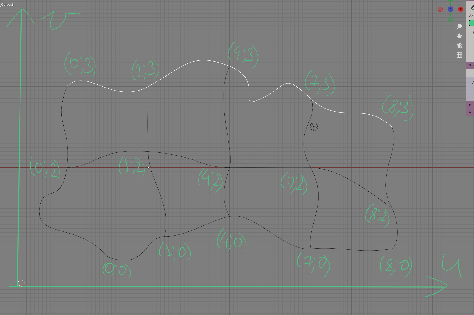
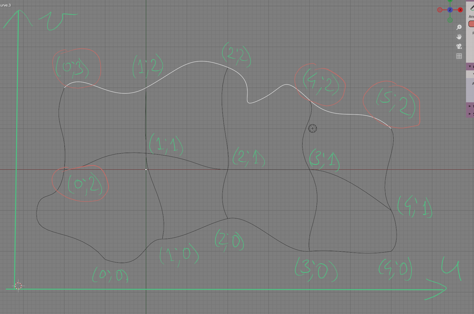
It only means that each U-curve must intersect V-curves at the same value of parameter of V-curves, and each V-curve must intersect all U-curves at the same value of parameter of U-curves.

Maybe it will be simpler to illustrate.
Good parametrization: (first number is parameter of U-curve at the intersection point, the second number is parameter of V-curve at the intersection point):
Screenshot_20210628_204916

Note that when you move from left to right, U value is changing by the same amount at all U-curves. And when you move from bottom to top, V-value is changing by the same amount at all V-curves.

"Bad" parametrization:
Screenshot_20210628_205316

@rendetto
Copy link
Contributor

rendetto commented Jun 28, 2021

OK got it. So my setup is fine - I placed the sections at the same parameters on both paths (0.0 ,0.3, 0.52, 0.76, 1.0) and still the interpolation is off.
I tried feeding the explicit T values but I got GEOMDL error:
SVGordon_Test002_ExactT

@portnov
Copy link
Collaborator Author

portnov commented Jun 28, 2021

Woh, interesting. Please post console output here.
Meanwhile, you can play with other implementations of curves.

@portnov
Copy link
Collaborator Author

portnov commented Jun 28, 2021

Can you share blend file?

@rendetto
Copy link
Contributor

I tested the Explicit T values on my test file. Now the surface goes through the sections really well, but there is brake in the internal continuity. I used the "zebra" matcap to illustrate the effect.

SVGordon_Test002_ExplicitT

Maybe there is no way to interpolate the sections so perfect and in the same time to maintain the initial degree and control points structure of the source curves. Nevertheless I like the initial result being really tight on the contour curves and in the same time identical to the source curves structure and degree. In many cases that's more important than interpolating exactly through the sections.

I wanted to compare this particular setup as being identical to the Birail case. Mainly because I have it set with the Birail node where I get somewhat better (but again not exact) interpolation of the sections. The curious thing with the Birail node is that the best result is achieved using exactly 5 VSections(an equal number to the source curves in V direction) as control parameter and everything above created somewhat bigger deviation (but better parametrization regarding the initial placement of the sections).

@portnov
Copy link
Collaborator Author

portnov commented Jun 30, 2021

Maybe there is no way to interpolate the sections so perfect

AFAIK there is a way, but it's too complicated for me to implement in nearest future :)

@rendetto
Copy link
Contributor

Wow, it will be great if you implement it at some point in time.
Is there a paper that can be read about it? I'm curious regardless of being just an artist.

One method I know of is implemented in the TiGL library and also adapted for python in CurvesWB in FreeCAD - but it's a reparametrization method and also produces lots of control points. It's smooth but sometimes the resulting surface can get really wavy.

@portnov
Copy link
Collaborator Author

portnov commented Jun 30, 2021

As far as I understand, it is possible to do reparametrization as follows:

  • write down pairs of T-values: (existing T, wanted T)
  • compose a smooth function which interpolates these pairs. Most probably with Legendre polynoms.
  • Apply methods described in p.6.4 "Reparameterization of NURBS Curves and Surfaces" of "The NURBS Book" to reparametrize the curve with that interpolating function.

I did not dig into TiGL / FreeCAD implementation, but I suspect that they use the same general approach. It looks simple when described in general words, but it involves quite significant amounts of mathematics :)

The good thing about this approach is that it uses smooth interpolation. My current approach, in turn, is much simpler, but it uses picewise-linear interpolation:

  • Cut the curve into segments at original T values
  • Use (trivial) linear reparametrization for each segment
  • Concatenate resulting segments into new curve.

@rendetto
Copy link
Contributor

Thanks a lot. I'll do a search on those topics.

As for TiGL, this is the paper I know of https://arxiv.org/pdf/1810.10795.pdf . Hope you can find it useful in some way.

@portnov
Copy link
Collaborator Author

portnov commented Jul 1, 2021

Interesting. It uses the following approach:

  • To make a smooth interpolation function (sigma), a B-spline is used.
  • Instead of exact reparametrization "a la NURBS book", it samples composed function f(sigma(t)) at number of points and approximates resulting points with a new nurbs curve.
  • for this approximation, "a hybrid approximation / interpolation technique" is used.

So yes, this is smooth reparametrization, i.e. it preserves curvature continuity; but the resulting surface follows given curves only approximately, while passing exactly through intersection points. Though I think approximation precision should be adjustable, so by some setting you should be able to have a "precise enough" surface.

@rendetto
Copy link
Contributor

rendetto commented Jul 1, 2021

The control it gives is by ramping up some precision tolerance value and a target maximum of control points (which could be not the best approach since you can never get exactly what you want). The "precise enough" result can work in certain cases, but when the goal is high precision/quality surface modelling it hits its limits because of the oscillation and the unpredictable control vertices structure/degree/knot vector.

FCGordon

Also it could be a real disaster, but that I guess is a matter of source curves distribution.

FCGordon_waves

@portnov
Copy link
Collaborator Author

portnov commented Jul 1, 2021

I tested the Explicit T values on my test file. Now the surface goes through the sections really well, but there is brake in the internal continuity. I used the "zebra" matcap to illustrate the effect.

SVGordon_Test002_ExplicitT

By the way, I'm not sure at this scale, but it looks like you have curve intersection point very near of "even" T parameter value. Due to cut-and-join approach I described above, this leads to two rows of control points very near one another.

@rendetto
Copy link
Contributor

rendetto commented Jul 1, 2021

It's not just near - the sections touch the paths precisely at the provided T values. I was assuming that this is the way to construct the curve net. But there are no coincident control points at the left part where the zebra is zig-zag-ing.
You can check it here:
SVGordon_Test002c_1.zip

I guess the continuity break comes from the knot multiplicity there. If you increase the Mesh Viewer density this break becomes even clearer.
SVGordon_Test002_ExplicitT_ContinuityBreak

@portnov
Copy link
Collaborator Author

portnov commented Jul 4, 2021

I investigated this issue for a while. It seems, with current implementation of reparametrization, it is not possible to automatically have smooth continuity every time.

In some cases it is possible to achieve good results by "manually" removing excessive knots. In current state of this branch, you can pass result of Gordon node through Formula node with the following formula: surface.remove_knot('V', 0.25, 2). It means remove knot V=0.25 two times. In your example setup, this gives good result for me. But in general, there is no guarantee, so I don't think it's good idea to do so automatically.

@rendetto
Copy link
Contributor

rendetto commented Jul 4, 2021

Thanks a lot! It looks a lot better now. I was planning to make a feature request of removing knots, but saw you already started implementing it :)
SVGordon_Test002_ExplicitT_RemovedKnots

I agree that the manual intervention is the appropriate approach. An automatic one could solve a number of cases but never all the cases, so tweaking the things manually is a very good option.

@portnov portnov changed the title [WIP] On Gordon NURBS surface Surface from Net of Curves Node (Gordon Surface) Jul 4, 2021
@portnov portnov marked this pull request as ready for review July 4, 2021 08:07
@portnov portnov merged commit 95102d4 into master Jul 4, 2021
Sign up for free to join this conversation on GitHub. Already have an account? Sign in to comment
Labels
Projects
None yet
Development

Successfully merging this pull request may close these issues.

2 participants