-
Notifications
You must be signed in to change notification settings - Fork 33
DIfferences betwen how ISIS and USGSCSM handle fractional lines in line scan sensor models
While comparing ALE/USGSCSM and ISIS sensor models for LRO NAC, MRO CTX, Kaguya TC, and MEX HRSC; we found that ISIS and USGSCSM handle fractional lines differently! The following explains how each piece of software works and then what that means at a higher level.
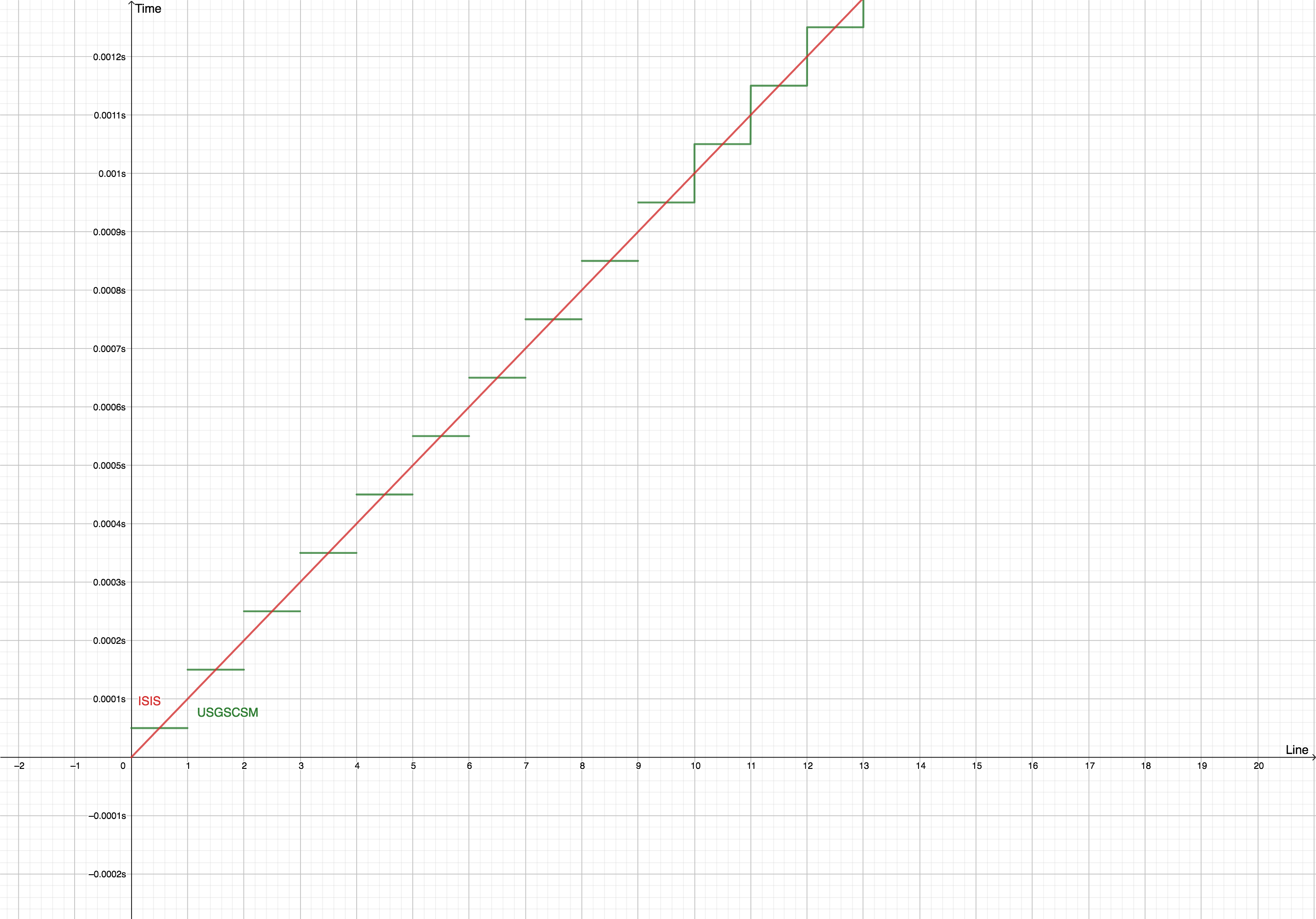
In the USGSCSM Line Scan Sensor Model, we assume that each line was exposed a single point in time. That means the exterior orientation of the sensor for line 1.2 and line 1.8 are the same. If the sensor is located at (1200, 239, 2954) for line 1.2, sample 1; then the sensor is also located at (1200, 239, 2954) for line 1.8, sample 1. If you plot the image time vs the line, you will get a stair-step function.
Different fractional lines are mapped to different down-track coordinates in the focal plane. If line 1.2, sample 1 maps to (0.02, 0.1) on the focal plane; then, line 1.8, sample 1 may map to (0.08, 0.1) on the focal plane.
In the ISIS line scan and variable rate line scan sensor models, we do not assume that each line was exposed at a single point in time. That means the exterior orientation of the sensor for line 1.2 and line 1.8 are the not same. If the sensor is located at (1200, 239, 2954) for line 1.2, sample 1; then the sensor may be located at (1292, 245, 2960) for line 1.8, sample 1. If you plot the image time vs the line, you will get a linear or piecewise-linear function.
Different fractional lines are mapped to the same down-track coordinates in the focal plane. If line 1.2, sample 1 maps to (0.05, 0.1) on the focal plane; then, line 1.8, sample 1 will also map to (0.05, 0.1) on the focal plane.

The fundamental difference is with how individual lines can be projected to the ground. In USGSCSM, each line is projected down as the FOV for the full line at a single time. In ISIS, each line is projected down as the FOV for just the center of the line across the full exposure duration of the line. This means in USGSCSM adjacent lines are adjacent footprints and in ISIS adjacent lines are continuations of the same continuous scan.
When line scan observations are planned, the spacecraft altitude, velocity, and exposure duration are carefully controlled so that footprints for adjacent lines are effectively right next to each other on the ground. This results, in both approaches producing nearly the same output.
Though rare, there are situations in which the spacecraft altitude, velocity, and exposure duration are not selected to create continuous ground footprints. In these cases, the USGSCSM method is superior because it properly models the discontinuous footprint. To account for this, ISIS has a separate program called pixel2map and separate calls in the sensor to generate the true pixel FOVs. Below is a good pair images from the pixel2map documentation that shows what this case looks like. The first image assumes a continuous scan and the second properly models the discontinuous scan.