HW Expander design
In the previous phase of the development cycle we have designed and manufactured so called capes for the BeagleBone Black devices for the following purposes:
-
We wanted to power the units from 12VDC source instead of 5VDC
-
Better access for I2C interface
-
We had needs for easy-to-use ports to attach additional circuits to the main board
We call them expanders, and after the cape installment these expanders could be use to extend the functionality of the BeagleBone unit.
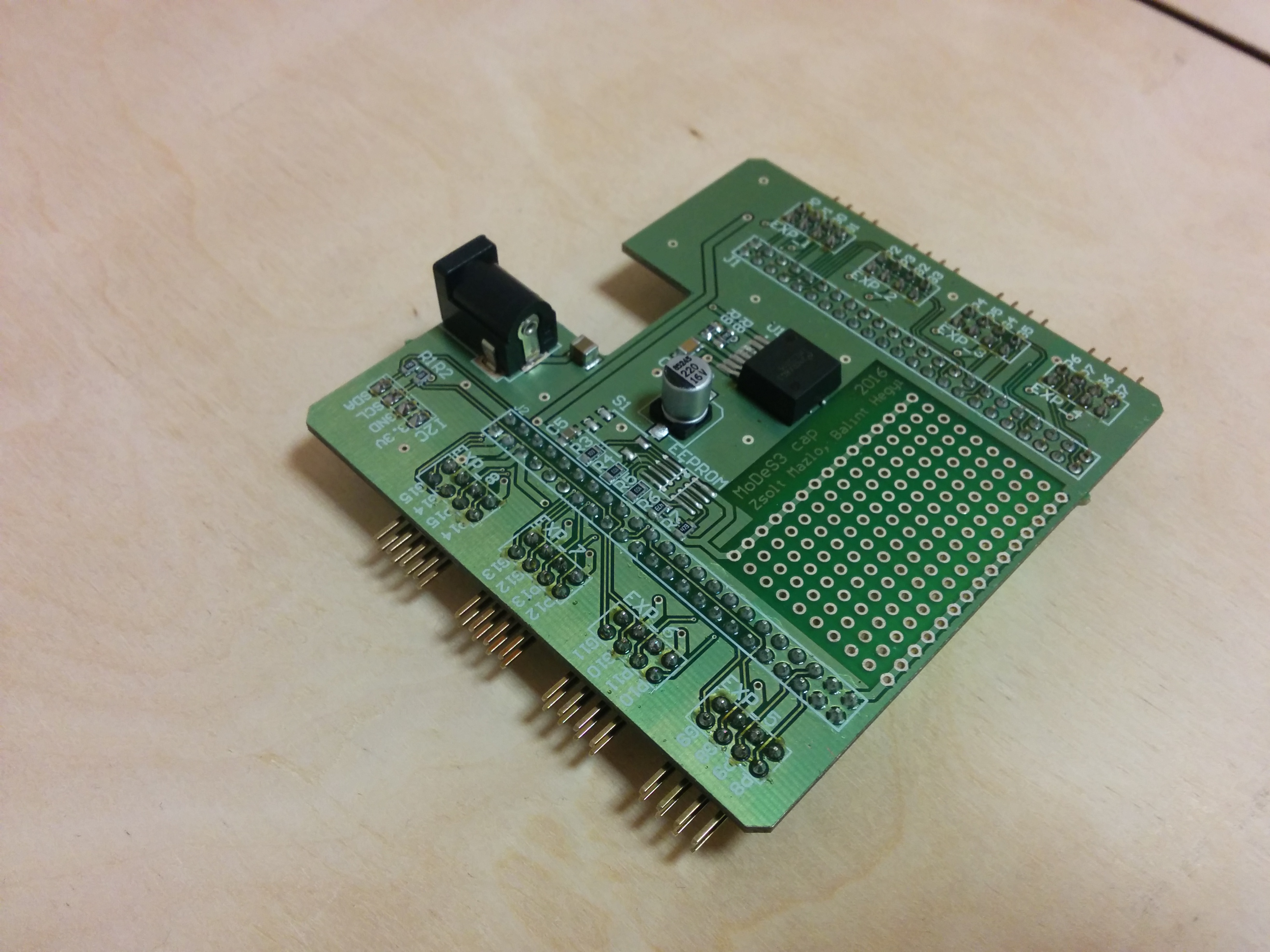
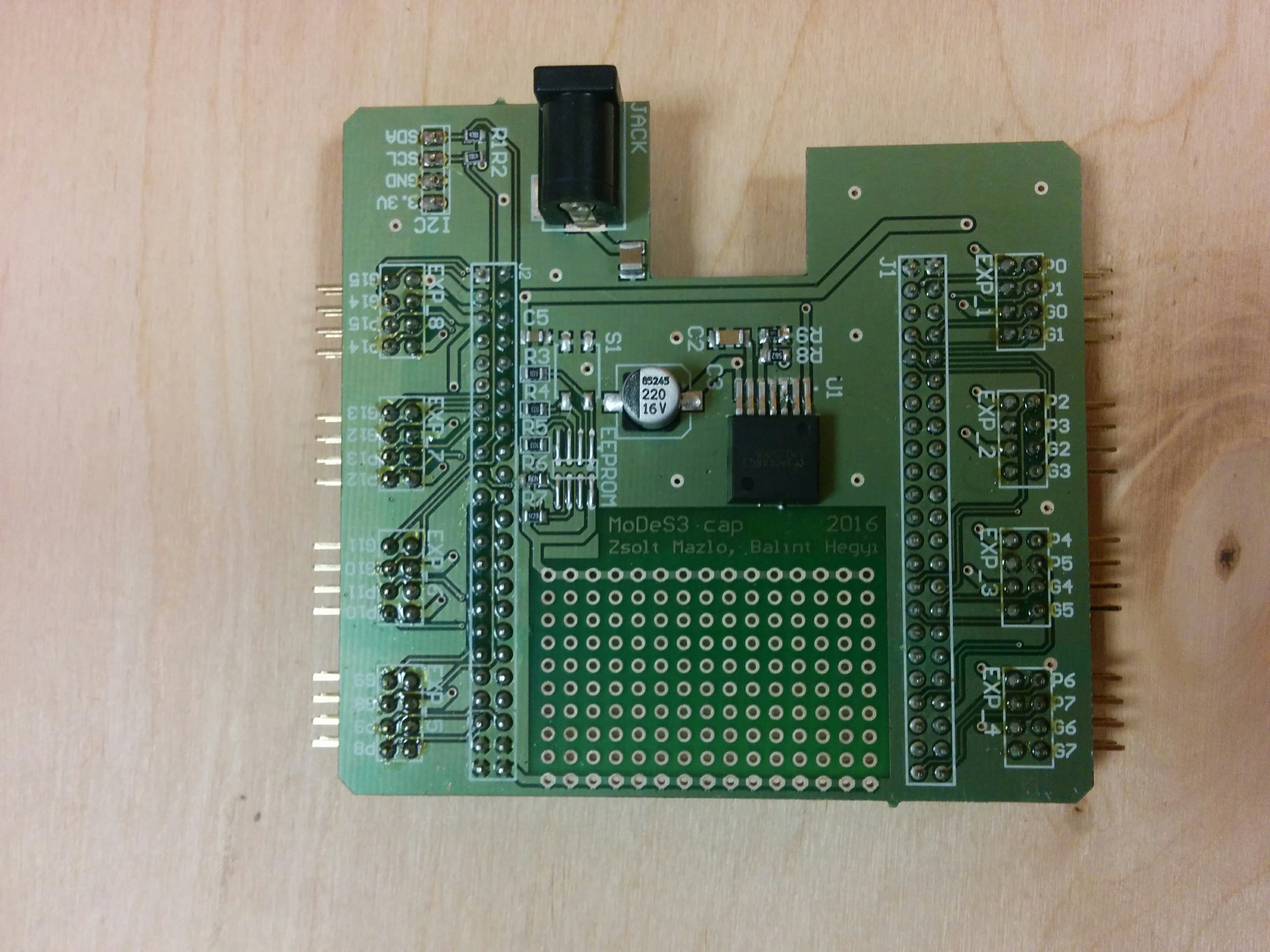
There are 8 general purpose expander slots on each cape, therefore each slot has the following pinout (front view).
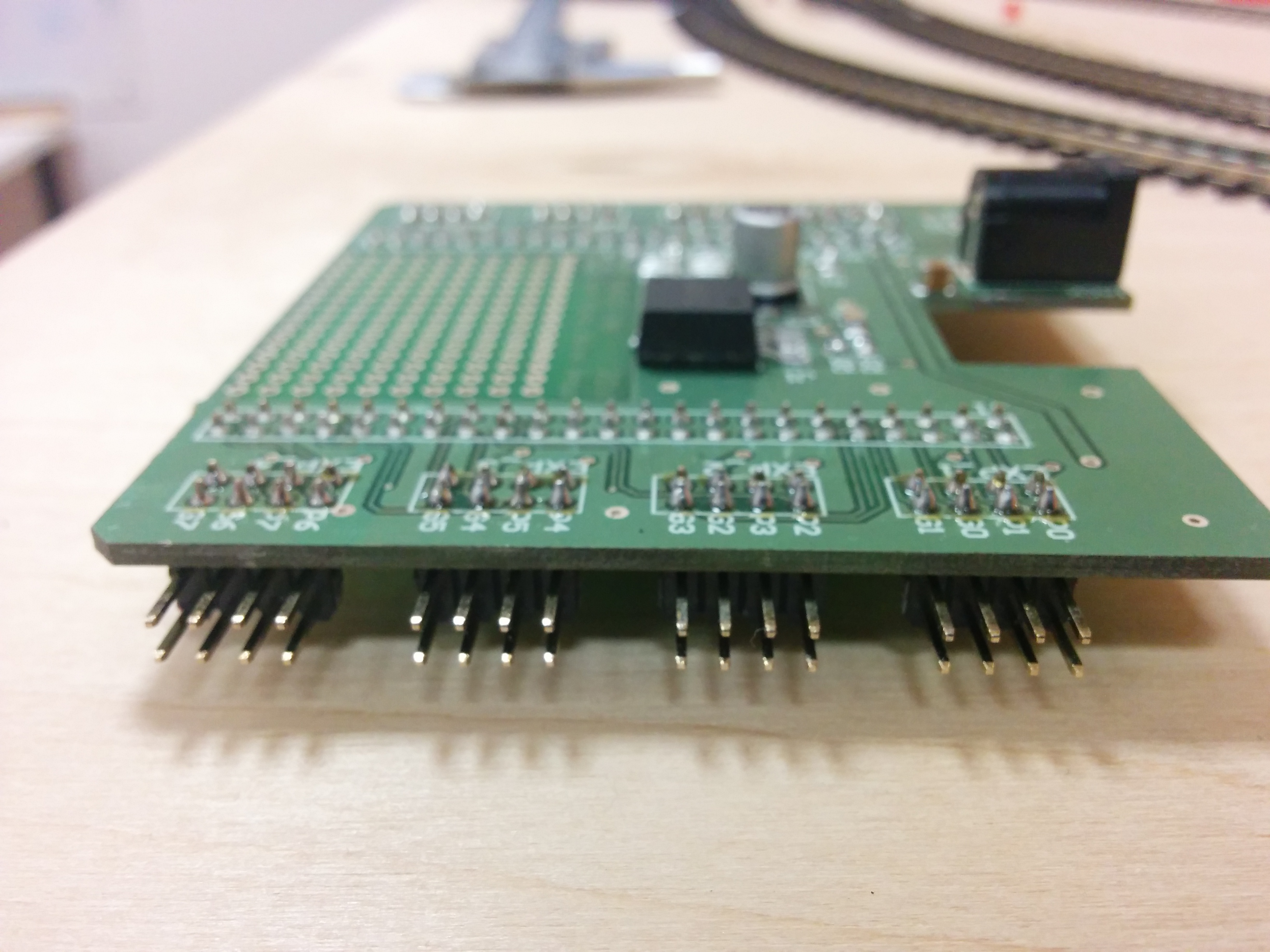
pin3 |
pin2 |
pin1 |
pin0 |
3V3 |
5V |
Gnd |
12V |
The upper row of each connector is dedicated for GPIO connections. Two of the GPIO pins connected to the application processor, and two of the GPIO pins are connected to the PRU unit. The pins connected to the application processor are labeled G0..G15, and the pins connected to the PRUs are called P0..P15.
With this setup, the PRU and the application processor can cooperate on hardware level. Also, if we want we could use the P0..P15 GPIOs from the application processor as well.
Before applying input on these pins, you must ensure that they are configured as inputs and the highest voltage level is not higher than 3.3VDC. Higher voltages on these pins could destroy the BeagleBone unit.
On the BeagleBone systems we can use the sysfs interface, where we can set the direction of the GPIOs, set or read value of the pins, and other several features as well. In order to use this feature, we need to know the ID of each pin, which are enlisted in the following table.
| Expander | GPIO name | GPIO number |
|---|---|---|
Expander 1 |
P0 |
86 |
P1 |
88 |
|
G0 |
67 |
|
G1 |
66 |
|
Expander 2 |
P2 |
87 |
P3 |
89 |
|
G2 |
69 |
|
G3 |
68 |
|
Expander 3 |
P4 |
76 |
P5 |
77 |
|
G4 |
11 |
|
G5 |
10 |
|
Expander 4 |
P6 |
70 |
P7 |
71 |
|
G6 |
79 |
|
G7 |
78 |
|
Expander 5 |
P8 |
20 |
P9 |
7 |
|
G8 |
2 |
|
G9 |
3 |
|
Expander 6 |
P10 |
110 |
P11 |
112 |
|
G10 |
51 |
|
G11 |
48 |
|
Expander 7 |
P12 |
111 |
P13 |
113 |
|
G12 |
31 |
|
G13 |
50 |
|
Expander 8 |
P14 |
115 |
P15 |
117 |
|
G14 |
60 |
|
G15 |
30 |
With the following script, you can set up a GPIO as an output, and set its value LOW or HIGH. All GPIO need to be exported before its usage, and if it is no longer needed, it must be unexported. These nodes of the file-system can only be written by root.
echo 30 > /sys/class/gpio/export
echo "out" > /sys/class/gpio/gpio30/direction
echo "0" > /sys/class/gpio/gpio30/value
echo "1" > /sys/class/gpio/gpio30/value
echo 30 > /sys/class/gpio/unexport