-
Notifications
You must be signed in to change notification settings - Fork 0
GPIO
On your UP there is a 2x40 header like Raspberry Pi one. That pins are managed by this node.
Please refer UP website to learn more about your board.
This node supports two modes:
- Digital Output, true/false output
- Digital Input, true/false input
-
Subscribed:
/upboard_ros/gpio/write(upboard_ros/ListGpio), list of digital out commands -
Published:
/upboard_ros/gpio/read(upboard_ros/ListGpio), list of digital in readings
-
frequency(float, default: 100), set in Hz reading updates -
frame_id(String, default: "base_link"), set frame_id
You can configure pins by copying and editing following lines in a .yaml file.
upboard_ros:
  DigitalOut: [<pin>,<pin>,...]
  DigitalIn: [<pin>,<pin>,...]
<pin> is a number from 1 to 40 according with your board pinout.
You can find an example file used for tests in config folder.
You can run this node by typing:
rosrun upboard_ros gpio_node
To turn on pin 22:
rostopic pub /upboard/gpio/write upboard_ros/ListGpio "{header: auto, gpio:[{pin: 22, value: 1}]}" --once
To turn off pin 22:
rostopic pub /upboard/gpio/write upboard_ros/ListGpio "{header: auto, gpio:[{pin: 22, value: 0}]}" --once
rostopic echo /upboard_ros/gpio/read
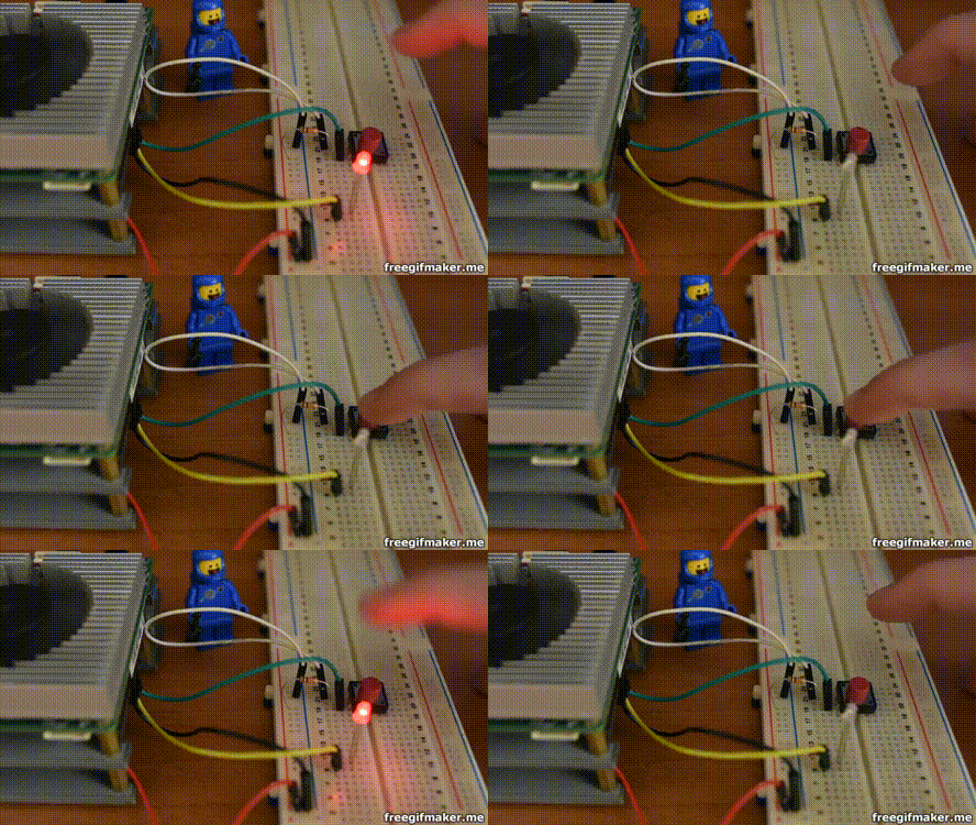
Reproduce following connections:

Then in terminal type:
roslaunch upboard_ros gpio_test.launch
Press button to change blink period.

Used GPIO are set to 0 when gpio_node is killed.
Max voltage for digital input is 3.3 volts.
Copyright (c) 2019 Giovanni di Dio Bruno under MIT license