How it works
The parallax effect requires two images.
Here's an intuitive demonstration of the parallax effect on an image (looking like a sad Australia):
In case images have parallel projection and rotate around a rotation point, the distance each point would move is proportional to the distance from that point to the rotation center.
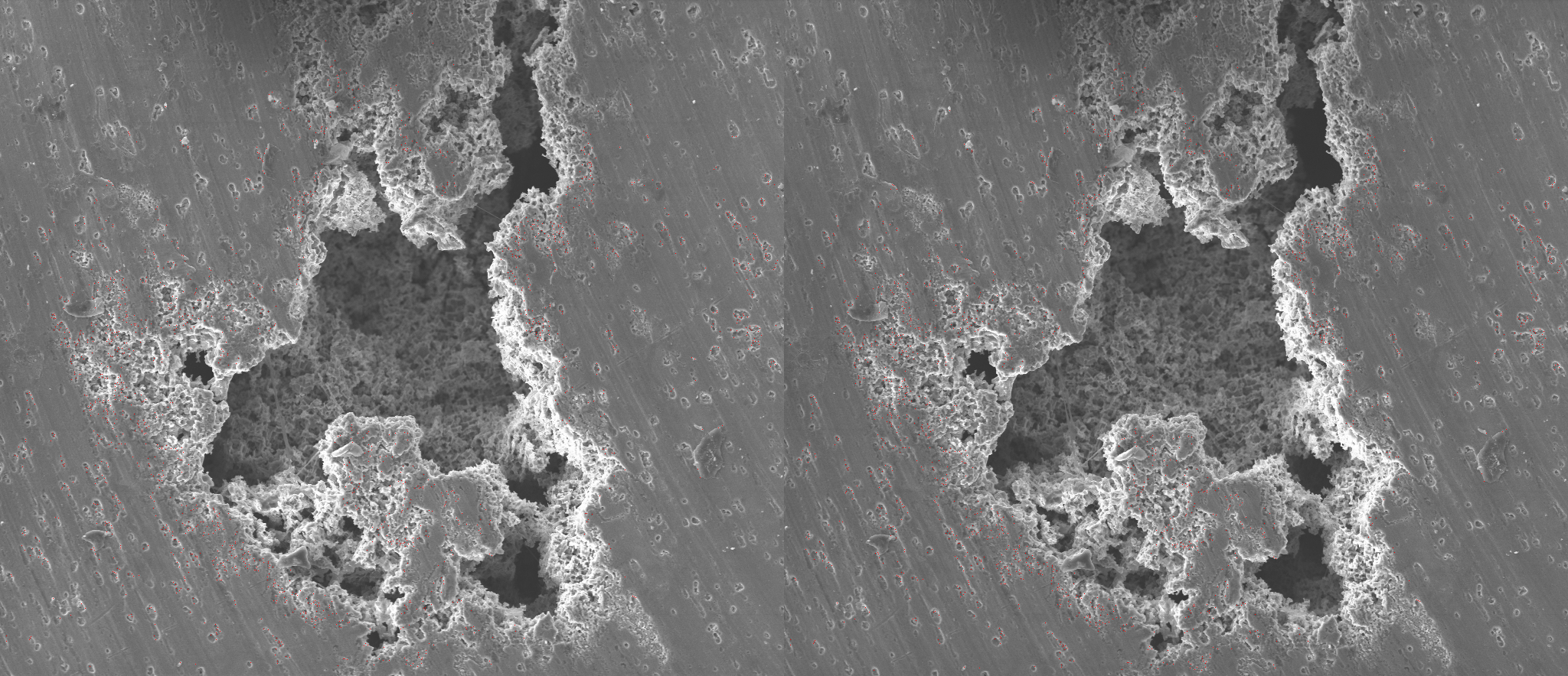
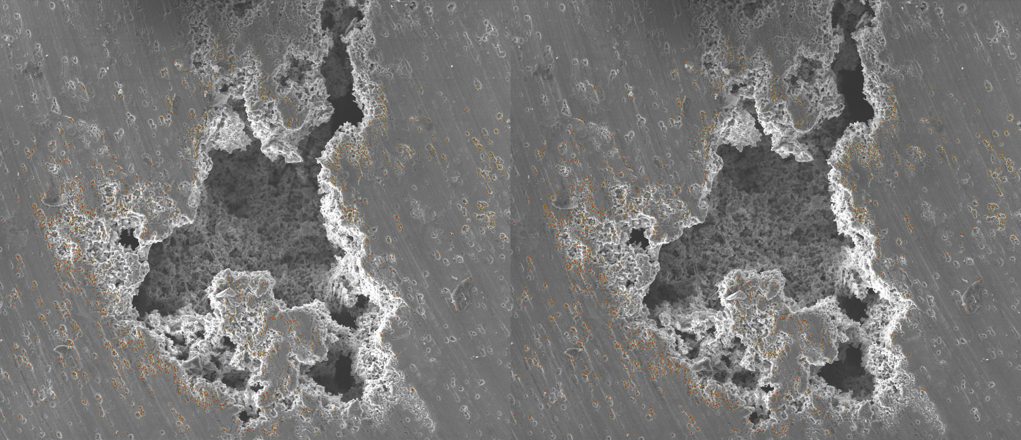
To determine the rotation axis, points are detected with the FAST keypoint detector.
This image illustrates points detected by FAST (highlighted with red):
For every FAST point, an ORB descriptor is created. An ORB descriptor is based on the image details around a FAST point and can be easily compared with another ORB descriptor.
Feature points are matched by comparing each feature point's ORB descriptor on image A with every feature point's ORB descriptor on image B.
Only point matches that are close enough are kept.
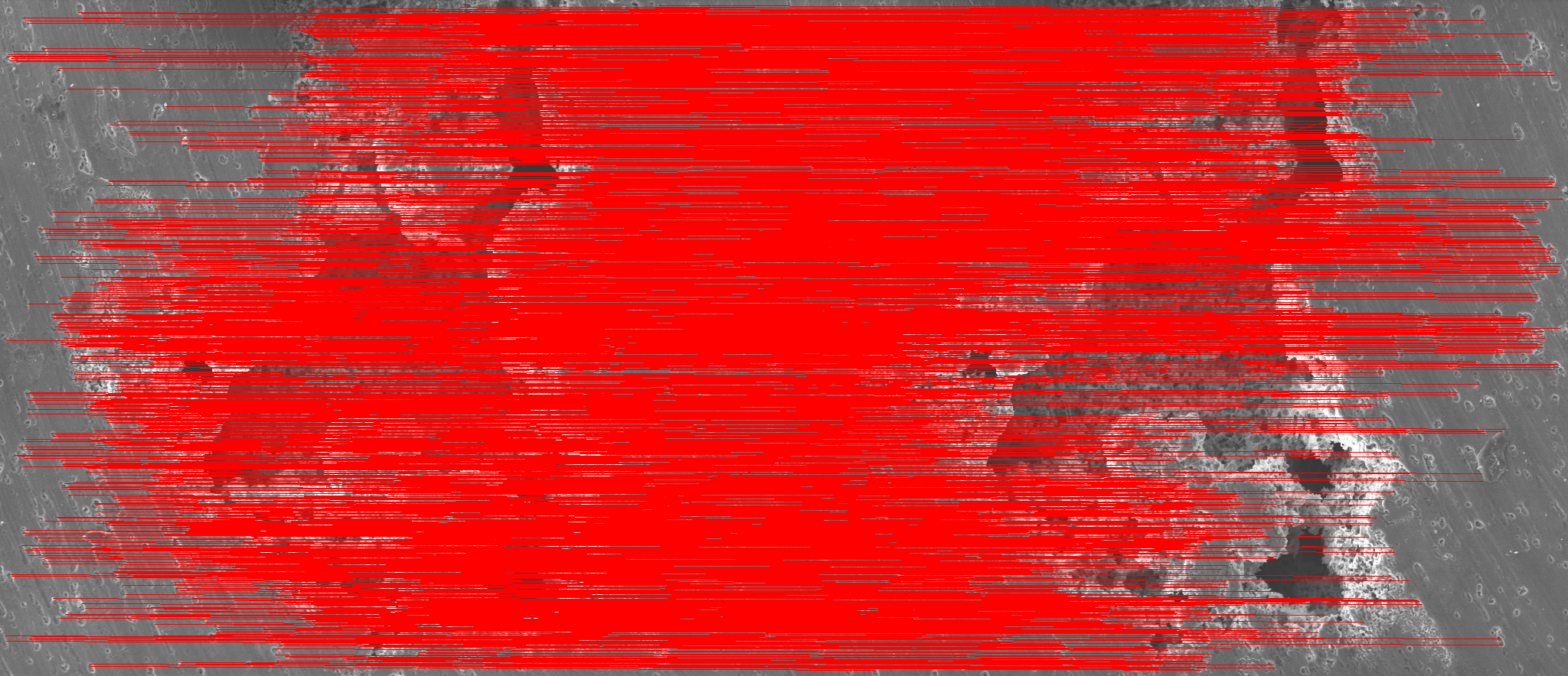
Here's an example with lines connecting all point matches from image A to image B:
Using the RANSAC method, find the set of points that all match the same Fundamental matrix. In some cases, there's no clear consensus set (or multiple different sets) - which might cause the algorithm to either fail, or produce garbage results.
The previous step will give some false positives, which should be filtered out.
Here's an example with lines connecting all filtered FAST points from image A to image B (note the difference with the image from Step 2):
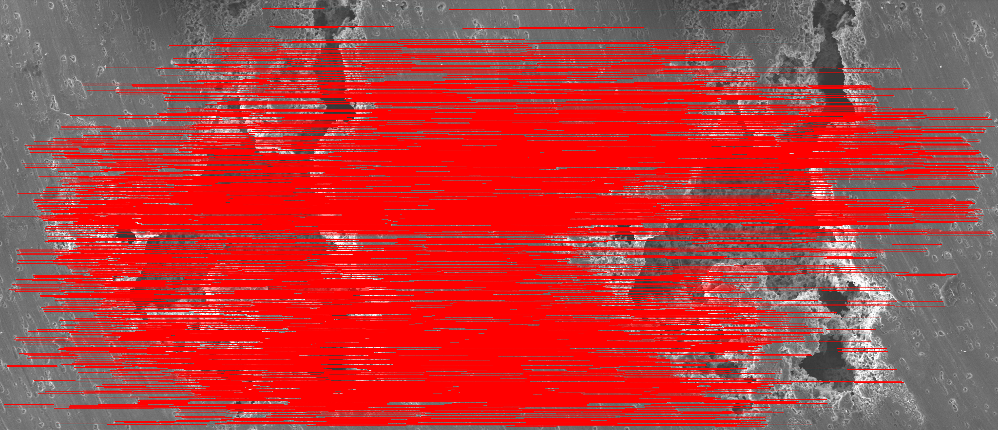
or the same matches, but drawing lines in the image coordinates:
The fundamental matrix significantly affects the next step, improving both performance and reliability of the reconstruction process.
In perspective images, the fundamental matrix is further processed to minimize projection error.
Now that the fundamental matrix has been established, it's time to start the most time-consuming process: for every pixel on image A, find a matching pixel on image B.
This is done by using image cross-correlation for areas in image A and image B.
Cross-correlating all pixel between images A and B is prohibitively time-consuming. This would also lead to a lot if false positives, especially if the image contains repeating textures.
Cybervision uses a better approach to only cross-correlate each pixel from image A with a small area in image B - where a match is most likely to be found:
-
Each pixel from image A is only searched in a narrow "corridor" in Image B (called an epipolar line - a "corridor" is a epipolar line that's a few pixels wide).
This "corridor" matches the direction calculalated on the previous step (determined by a point's epipolar line).
-
A scale pyramid is used to perform cross-correlation on a downscaled image first.
Then, on each larger scale the depth (distance) between neighboring pixels is used to approximate where a match is most likely to be found.
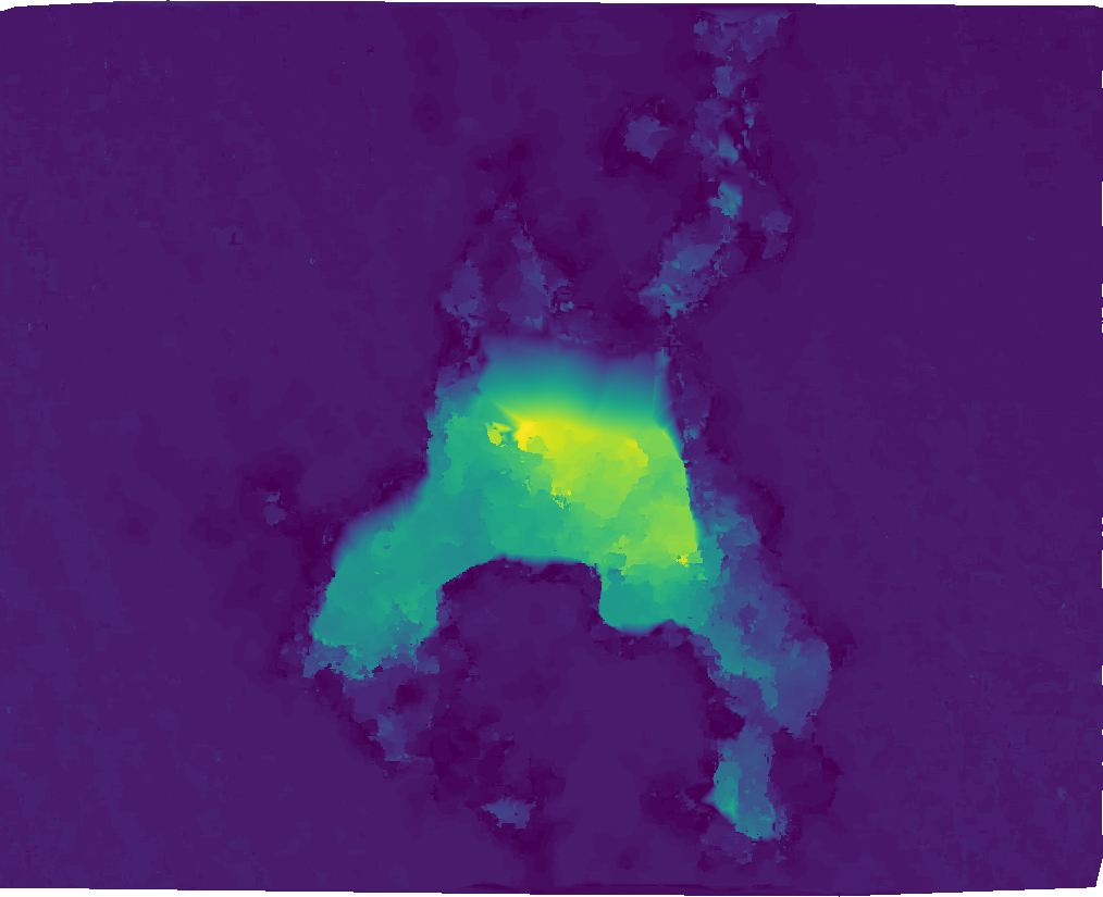
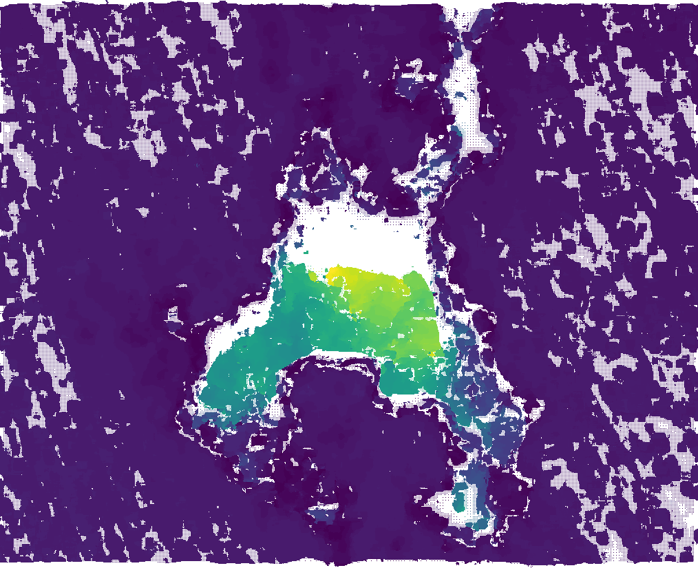
After the cross-correlation process completes, the resulting surface will look like this (no reliable correlation could be found in the blank areas):
For parallel projection, the distance a point moves between images (strength of the parallax effect) determines the point's depth coordinate.
For perspective (photo) projection, the process is a bit more complex:
- Build "tracks" - paths for points that appear on multiple images.
- Determine relative positions of the cameras:
- Using the fundamental matrix for the "initial pair" of images - images that have the highest number of matches;
- Then, continue adding images by choosing an image that has the highest number of triangulated 3D points
- Run an algorithm that determines a point's position in 3D space from all its projections
- Finally, run a bundle adjustment refinement process to minimize reprojection error.
If interpolation is enabled, a 2D Delaunay triangulation is done for every projection.
Then, the 2D projection is converted into 3D by using adding a depth coordinate.
Finally, delete any mesh triangles that obstruct visible points.
Using the qhull library, convert points into a 3D mesh.
At this moment, the surface can be saved as a Wavefront OBJ file, binary Stanford Triangle Format file or interpolated to get a depth map image.
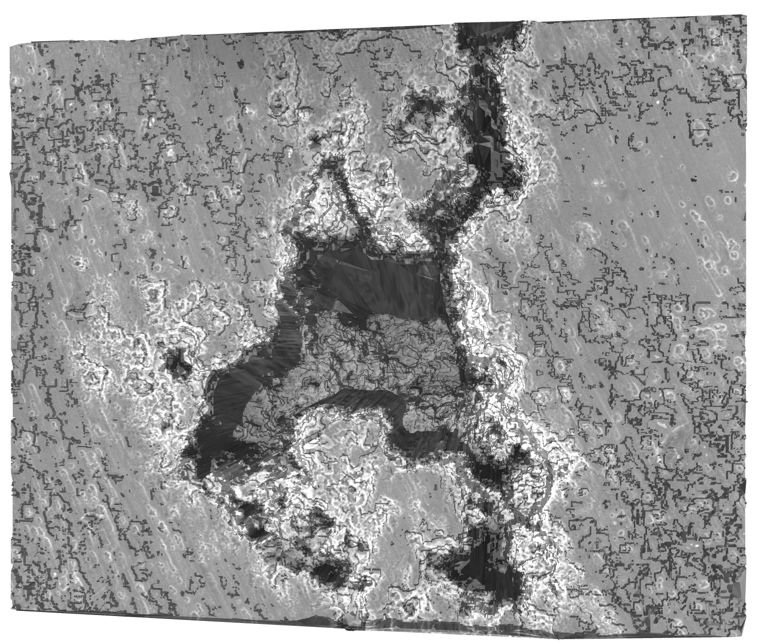
The end result will look like this: