-
Notifications
You must be signed in to change notification settings - Fork 42
Socket MCU
The MCU goes face down on both halves, with components toward the board. The solder holes are designed to make it hard to solder if you have it reversed. Once the MCU is in you can test that the LEDs all work, fix any issues, live without all the LEDs or scrap that board for a new one.
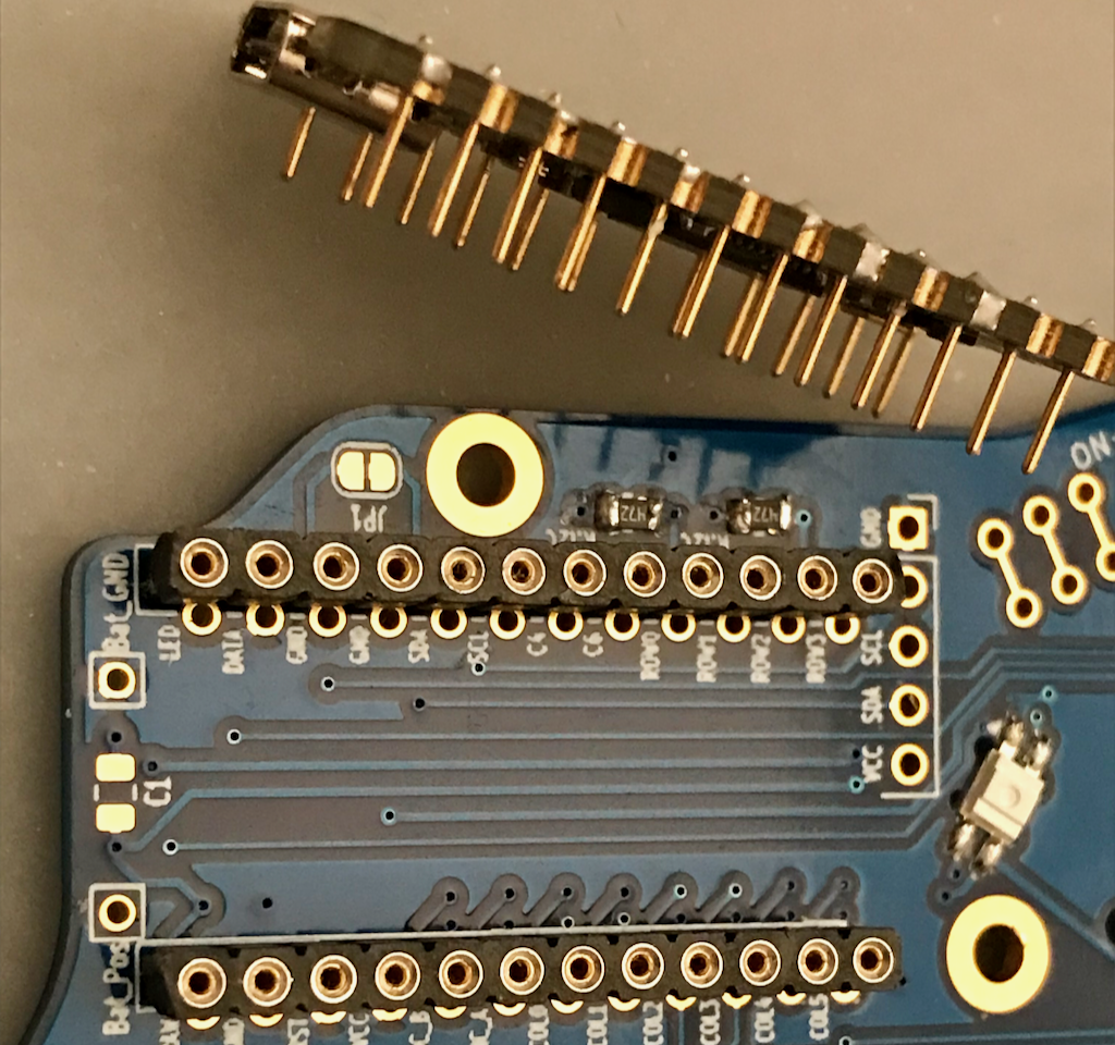
I'd socket it. Let me say that again. I'd socket it. The sockets are not the pins that come with the MCU, but rather a set of sockets rows and copper pins as shown:
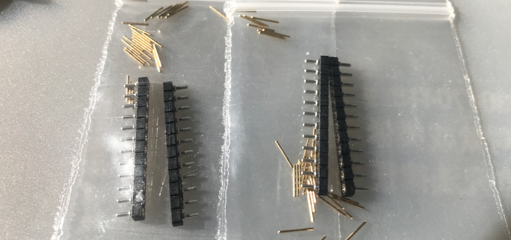
The sockets need to be soldered to the PCB top and aligned straight up, not canted over to the sides. The pins need to be soldered to the MCU and also aligned straight up not canted over to the sides.
A good way to achieve that is the following:
Put the sockets into their holes on the top of the PCB, but do not solder yet. Ensure the black part is sitting inside the white rectangles into holes that do not have a surrounding ring of exposed metal.
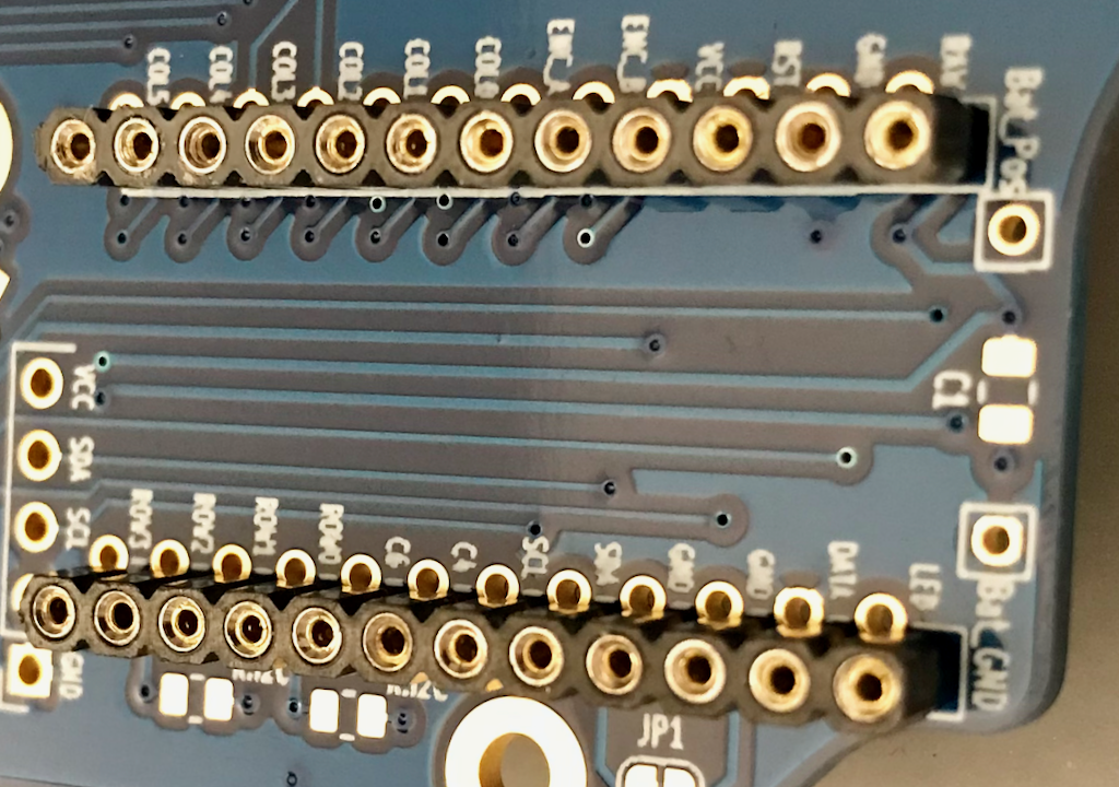
The underside of the sockets should come out where these is a ring of exposed metal, not where the hole is covered by solder mask. Note that only one row on each side has exposed rings around the holes. This is to make it difficult to mistakenly solder them incorrectly.
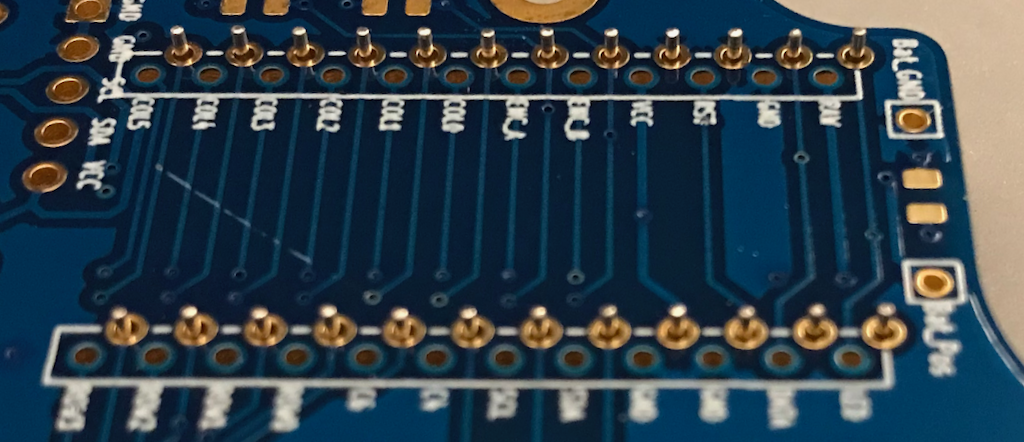
On the top, cover the holes of the sockets with tape. This is to help prevent solder from getting into them, and it will also help hold them in place. Do not tape over the bottom where we will be soldering them.
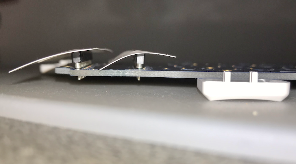
Note that one of these sockets is badly tilted off to the side. This is what we do not want after we have soldered them in place. To prevent that, we do the following.
Put a pin in each socket corner. You should feel it punch through the tape and then further down an additional click from the socket.
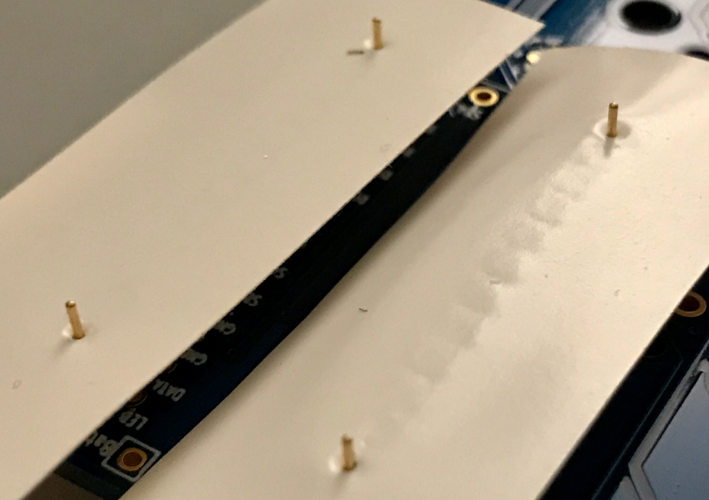
Now we can ensure that the socket holes are not spread apart at an angle but rather the right distance apart for the MCU.
NOTE: You need to be extra careful of not just the distance but also the angle if you intent to use a haptic module over the MCU. The mounting stud for the haptic module will form a wall to the side of the MCU, which will be very perpendicular to the board. Placing that screw and stud in place before socketing the MCU can help ensure the sockets are not both canted to that side, and thus allowing the MCU contacts to touch the metal suport stud.
Put the MCU on top of the four pins. If the pins are too far apart for the MCU holes, loosen the tape from the PCB, straighten the sockets so the MCU fits over the pins. As the sockets protrude past the board bottom, use something to keep the board off the table slightly so that the sockets can sit properly down on the board top.
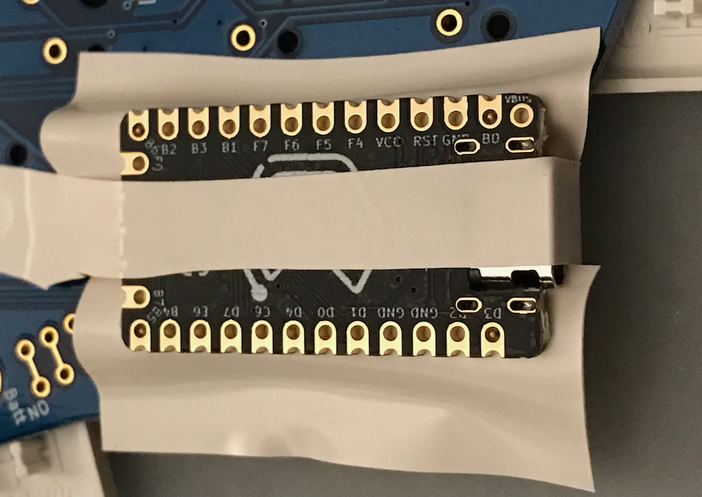
The MCU serves as a spacer to hold the sockets the correct distance apart at the top. Tape the MCU in place.
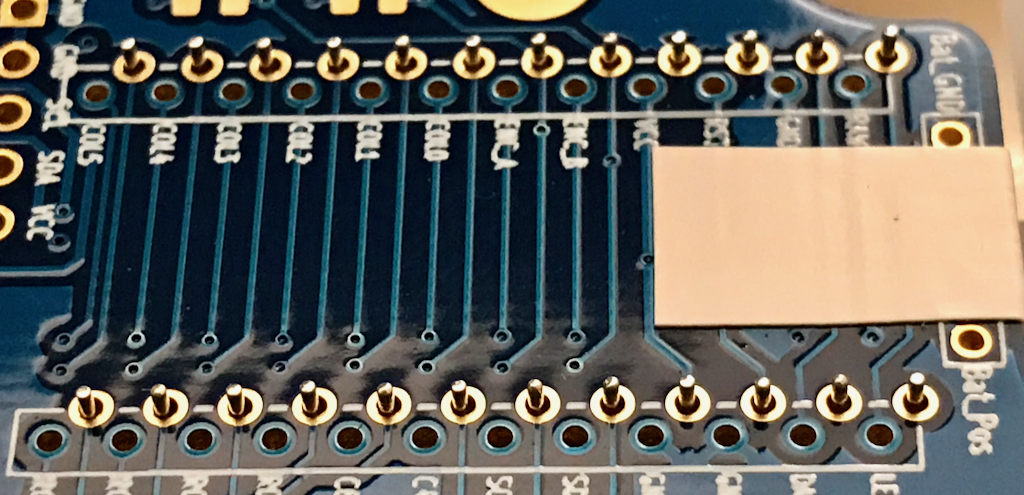
Solder each socket pin to the bottom of the board.
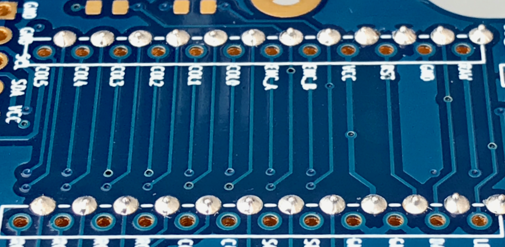
Now we can attach the brass pins to the MCU.
Push pins through the tape into the remaining spots of the MCU. Pressing them not just through the tape but down to click into the internal socket jaws. Once they are all in place, press on them to ensure they are all seated down to the same depth.
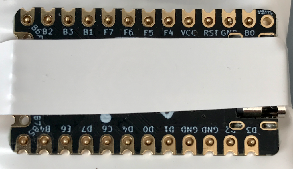
Solder all the pins to the MCU.
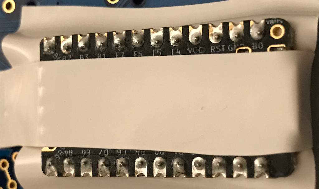
Gently pry the MCU off of the sockets, without bending any pins in the process. If you lift one end all the way off, you will have badly bent the pins on the other end. Instead, alternate lifting each end about a third of the way. Tweezers can be used carefully, or a nice wooden shim is ideal. Lift the tape away from the board first, so that you are not fighting it. You can also cut some of the tape back first to make in cleaner.
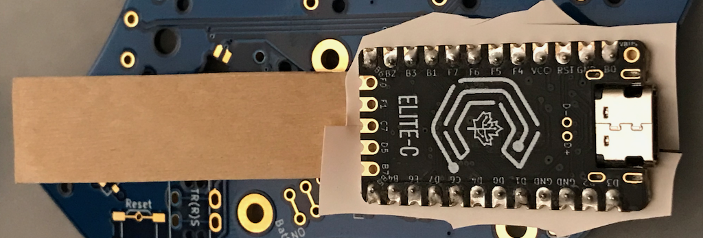
Remove the tape from the pins progressively so as to not bend any pins.
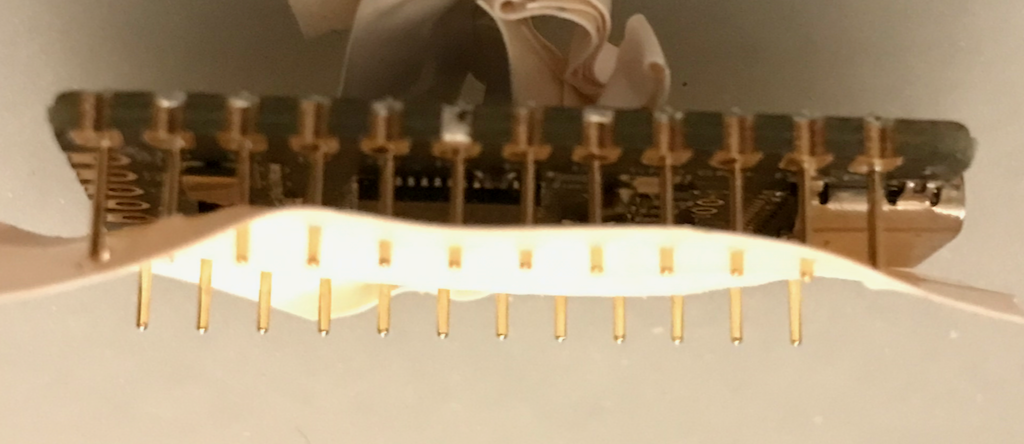
You now should have sockets attached to the board and pins attached to the MCU.
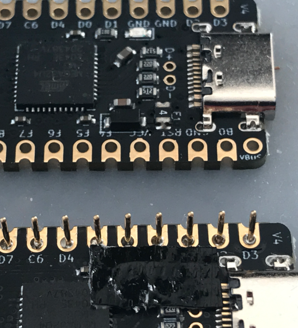
If you know that your MCU is working properly, you might tape over its LED before putting it back into the sockets. That LED is always on and may be more light than you want from the board. The LED for the elite-c is the white rectangle next to the GRD pin. Some tape gently pressed around it will prevent a persistent purple glow from your keyboard.
Gently and evenly push the MCU back onto the sockets. First ensure that all the pins are in the tops of the socket holes. Then press down evenly to insert and seat them. It is best to do this with the board on a solid surface and by pressing down evenly with both thumbs.
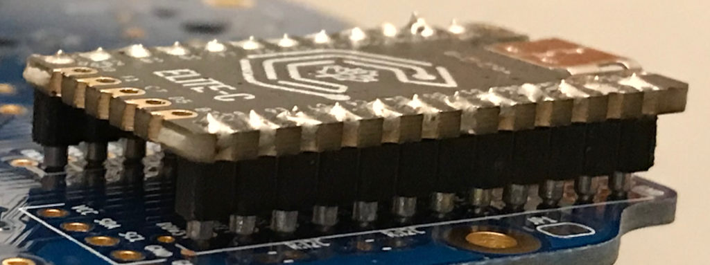
If you want, you can now test that the diodes and LEDS are soldered correctly by skipping ahead to the first part of the testing page. Or you can add the reset switch and TRRS jacks first, and then test the two sides connected.
Next: Wireless (Optional)