-
Notifications
You must be signed in to change notification settings - Fork 9
Kubo: Transforms
-
Overview
a. Background
b. Static Transform Structure
c. Sources of Measurement Error -
Static TF Frames
a. Current
b. Deprecated - Links
- Troubleshooting
ROS provides an easy way to understand the data taken by sensors, referenced to the world. Tf frames are automatic transforms applied to data collected from specific sensors so that the data can be visualized at its absolute location in the world. For more information about ROS transforms specifically, read REP 105 and Ros TF Documentation (see Links).
The following excerpt is taken from the ROS Wiki page on tf2:
static_transform_publisher x y z yaw pitch roll frame_id child_frame_id
Publish a static coordinate transform to tf2 using an x/y/z offset in meters and yaw/pitch/roll in radians. (yaw is rotation about Z, pitch is rotation about Y, and roll is rotation about X).
static_transform_publisher x y z qx qy qz qw frame_id child_frame_id
Publish a static coordinate transform to tf2 using an x/y/z offset in meters and quaternion.Unlike in tf, there is no period argument, and a latched topic is used.
One difficulty in measuring the transforms for each sensor is that the tractor is usually in the way of easily measurements. To get around this, a transform is defined between /base_link (the tractor) and /hood (the sensor mount). The origin of the sensor mount is shown in the image below:

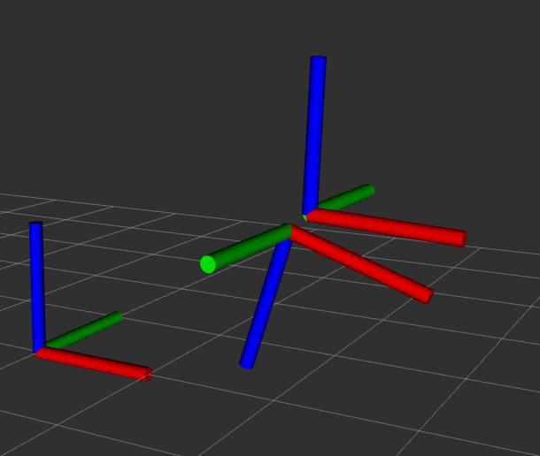
The subsequent transforms for sensors are determined from CAD to this point. The origins of the two lidar transforms defined are shown below, represented with basic shapes:
| UXM-30LX Lidar | Lidar X |
|---|---|
 |
 |
The transform tree outlined above results in the following diagram of transform relations:

To verify that the static transforms were calculated properly, the frames were displayed in rviz. In the images below, three frames are visualized: /base_link, /hood, and the relevant lidar frame:
| UXM-30LX Lidar | Lidar X |
|---|---|
 |
 |
- Measurements were taken using plumb bob and tape measure, probably generating inaccuracies
- Measurement points for sensors are assumed, not validated, because this information is difficult to find in documentation (with the exception of the UXM-30LX)
- Y positions of all sensors assumed to be 0 - perfectly centered
- These transforms change, to a certain extent, based on tire inflation
- Tractor base assumed level
- Tractor north is -y axis, tractor east is -x axis, and elevation is +z axis (RH coordinate system)
- RH coordinate system => left is positive, right is negative (for both /cmd_twist and /cmd_vel)
-
/cmd_twist: -1 max right, 1 max left -
/cmd_vel: -45 max right, 45 max left
-
-
/base_link: Point on the ground centered across and along the rear wheel axle. -
/hood: Point at the front of the lidar hood at the front of the tractor - see the figure below -
/laser: Sensor position & orientation for the UXM-30LX Lidar receiver -
/lidarx: Sensor position & oridntation for the Lidar X receiver (estimated) -
/image_raw: PointGrey Camera`**: Center of the lens cap of the PointGrey camera. -
/gps: Center of the base of the antenna on the level of the grey dividing line for the RTK GPS Antenna on the roof of the tractor. -
/imu: Phidget IMU - center of top of case.
-
/hemisphere:Beneath the 4-sided divot on the Hemisphere unit and on the level where the black plastic joins with the white plastic.
- Kubo localization.launch file (link)
- REP (ROS Enhancement Proposal) 105 (link)
- ROS TF Documentation (link)
- ROS TF Codebase Overview (link)
- ROS Navigation Tutorials (link)
- ROS TF Setup Tutorial (link)
- robot_pose_ekf node Documentation (link)
- Adding GPS to robot_pose_ekf node Tutorial (link)
When launching localization.launch, got error ERROR: cannot launch node of type [robot_localization/ekf_localization_node]: robot_localization