Firmware
This page contains instructions for updating firmware for the two types of embedded processors on Cassie.
- The ATTiny used in the Battery Management System
- The AT32UC3C used in the Pelvis and Leg Medullas
In all cases, make sure you have read and understood all the steps before proceeding.
⚠ CAUTION: Only update firmware if told to do so by a Agility Robotics representative.
Battery firmware files have ".elf" extensions and are flashed onto the microcontroller using Atmel Studio and the Atmel-ICE programmer. The IDC flat cable with 10-pin 50-mil connector and 6-pin 100-mil connector will be used to connect to the battery.

⚠ WARNING: Shock Hazard: This process requires the battery's electronics cover to be removed. With the battery electronics exposed, EXTREME CAUTION should be exercised to prevent foreign objects from entering the pack.
- Remove the battery's electronics cover with a screwdriver.
- Be careful to not strip the screws.
- Be careful to prevent any objects from entering the pack.
- Plug the IDC flat cable into the AVR port on the Atmel-ICE using the 10-pin connector at the end of the cable and plug the 6-pin connector into target battery's ISP header with the nub facing away from the battery terminals.

- Connect the Atmel-ICE to your computer via USB.
- Open Atmel Studio and navigate to Tools -> Device Programming.
- Choose the Atmel-ICE programmer from the drop-down Tool menu.
- Choose ATtiny167 from the drop-down Device menu.
- Choose ISP from the drop-down Interface menu.
- Click Apply then Read.
- Navigate to the Memories page and browse for the .elf file under Flash (16 KB).
- Click Program and check that the flash is successfully programmed and verified.
Medulla firmware files have ".elf" extensions and are flashed onto the microcontroller using Atmel Studio and the Atmel-ICE programmer. The 50-mil 10-pin mini squid cable will need to have a Molex Picoblade 8-pin connector crimped onto it in order to connect to a Medulla. Attach the numbered wires to the Picoblade housing as shown below.

Note that the red wire is wire 1, and the pin labeled 0 in the picture above is wire 10. Once the programming cable is made you can begin the following procedure:
- Plug the Picoblade cable into the AVR port on the Atmel-ICE and the target Medulla's JTAG port located near the RJ45 connector.

- Connect the Atmel-ICE to your computer via USB and apply power to the Medulla.
- Open Atmel Studio and navigate to Tools -> Device Programming.
- Choose the Atmel-ICE programmer from the drop-down Tool menu.
- Choose AT32UC3C1512C from the drop-down Device menu.
- Choose JTAG from the drop-down Interface menu.
- Click Apply then Read.
- Navigate to the Memories page and browse for the .elf file under Flash (512 KB).
- Hit Program and check that the flash is successfully programmed and verified.
Latest Pelvis Medulla ESI
Latest Leg Medulla ESI
ESI files have ".bin" extensions and are uploaded to the Medulla using the ET9000 EtherCAT Configurator software.
- Unplug the Pelvis Medulla from the Jetway Target PC (indicated below by the red arrow).

- Connect the now available RJ45 port on the Pelvis Medulla to your computer.
- Turn robot logic power on.
- Open the EtherCAT Configurator.
- Right click on I/O Devices and select Scan Devices....
- The Ethernet device on your computer connected to the robot should be checked.
- Click OK to add the device and hit OK to scan boxes.
- If no device is checked, verify your connection to the robot.
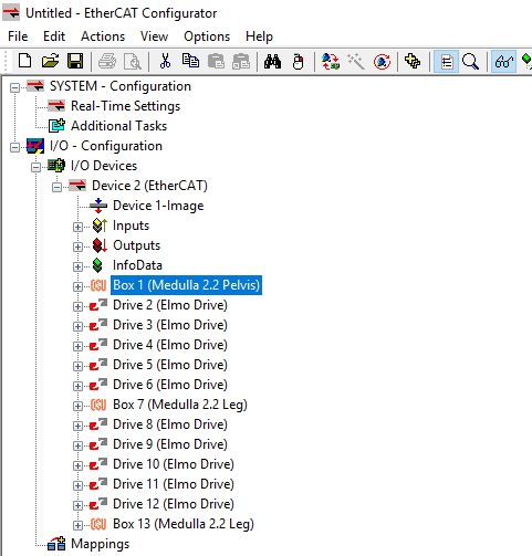
- All 13 slave devices should appear as shown below after scanning. If slaves are missing or out of order, check power and ethernet connections in the robot. Your device number may vary.
- Select your loaded EtherCAT Device
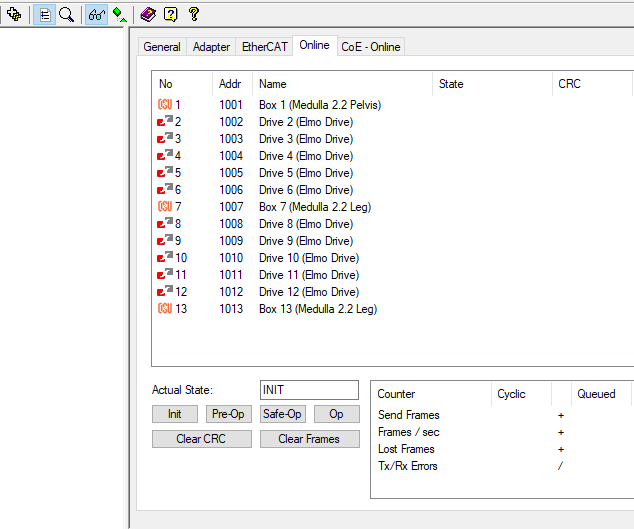
- Navigate to the Online window as shown below
- Change the master state to INIT and then back to OP.
-
Slave PDOs can now be viewed by expanding the menu using the "+" button next to the desired slave listed under your EtherCAT Device
- Medulla PDOs will update in real-time (with considerable filtering) but Twitters will not
-
Select the slave you would like to reprogram
- Navigate to the EtherCAT window, and open the Advanced Settings....
- Expand the ESC Access list.
- Expand the E2PROM list and select Hex Editor.
-
Click Read from File... and navigate to the ESI file you would like to write to the slave.
-
After confirming the EEPROM has been written, the changes will take effect after resetting the robot logic power.

- Introduction
- Limitation of Liability
- Warning Symbols in this Manual
- General Precautions
- Mechanical Precautions
- Maintenance Precautions
- Research and Development Precautions
- Battery Safety
- Mechanical Overview
- Electrical Overview